Eureka AIR delivers breakthrough ideas for toughest innovation challenges, trusted by R&D personnel around the world.

Connecting fastener

a fastener and connector technology, applied in the direction of threaded fasteners, screws, applications, etc., can solve the problems of narrow size range of usable fasteners and differing heights for supporting fasteners

Inactive Publication Date: 2005-02-24
MAX CO LTD
View PDF16 Cites 2 Cited by
  • Summary
  • Abstract
  • Description
  • Claims
  • Application Information

AI Technical Summary

Benefits of technology

[0063] As heretofore explained, since the connecting fastener according to claim 1 can guide the connecting fastener by supporting the guide part of the connecting band in the fastener magazine, it can be supported at a constant height regardless of the head shape of the fastener, and thus the supporting posture can be stabilized.
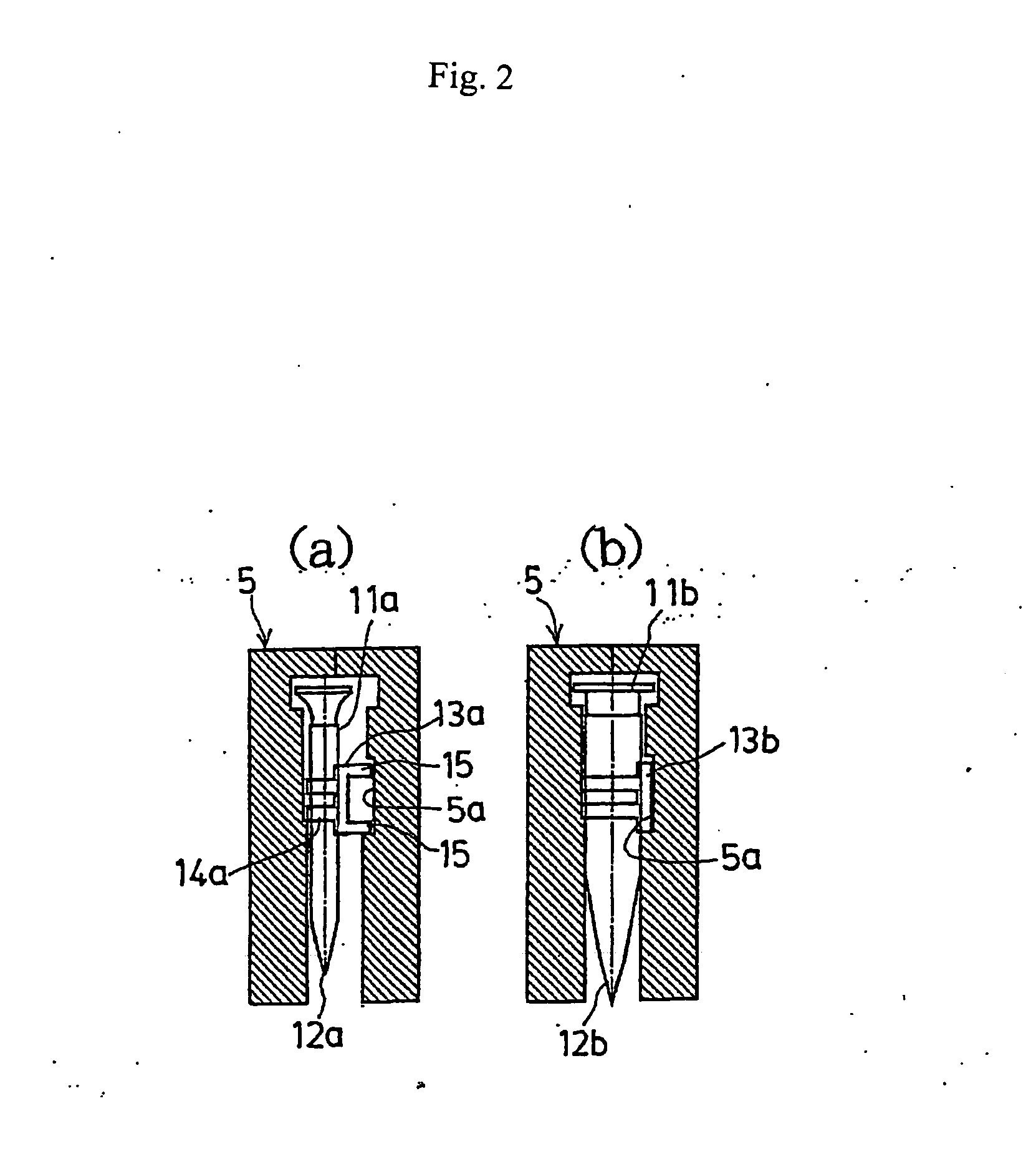
[0064] Since the connecting fastener according to claim 2 can support the connecting band by engaging the same with the guide groove formed in the fastener magazine regardless of the shaft diameter of the fastener by increasing or reducing the thickness of the connecting band according to the shaft diameter of the fastener, the connecting fasteners having various thickness can be loaded in one kind of the fastener magazine and the connecting fastener can be supported at a constant height.
[0065] Since the connecting fastener of claim 3 has the structure of providing the entire width of the connecting fastener constantly by increasing or reducing the partial thickness of the upper rim part, the lower rim part or the middle part between the upper and lower parts, or the like of the connecting band, the amount of using the resin material of the connecting band can be cut back as much as possible, and there is no risk of increasing the driving load at the time of fastening the screw or driving the nail because there is barely decline of the flexibility.
[0066] Since the connecting fastener of claim 4 has a structure such that the guide part is formed on the side surface of the connecting band and supported by the contact with the upper surface of the pressing plate provided in the fastener magazine, the connecting fasteners having various thickness can be loaded in one kind of the fastener magazine, the connecting fastener can be supported at a constant height, and the posture stability of the connecting fastener can be improved.
[0067] In the connecting fastener of claim 5, the connecting band for supporting the fastener serves as a guide part to be guided by the fattener machine such as the screw fastening machine and the nail driving machine. Moreover, lowering of the fastener is not prevented, because the adhesive member for supporting the fastener is ruptured at the time of ejection such as fastening or driving the fastener, or the like so as to release the support and be deformed appropriately. Thereby, inclined ejection of the fastener or bending of the fastener in the ejection path can be prevented.

Problems solved by technology

The conventional fastener magazine cannot support the head of the fastener having a head diameter smaller than the size of the lower part narrow width part of the fastener passage so that the fastener is dropped, and thus it cannot be used, and a problem is involved in that the size range of the usable fastener is narrow because a fastener having a thickness larger than the fastener passage width cannot naturally be loaded.
Moreover, a problem is also involved in that the height required to support the fastener differs if the head shape differs such as the flat head and the pan head.

Method used


Image

  • Connecting fastener
  • Connecting fastener
  • Connecting fastener

Examples

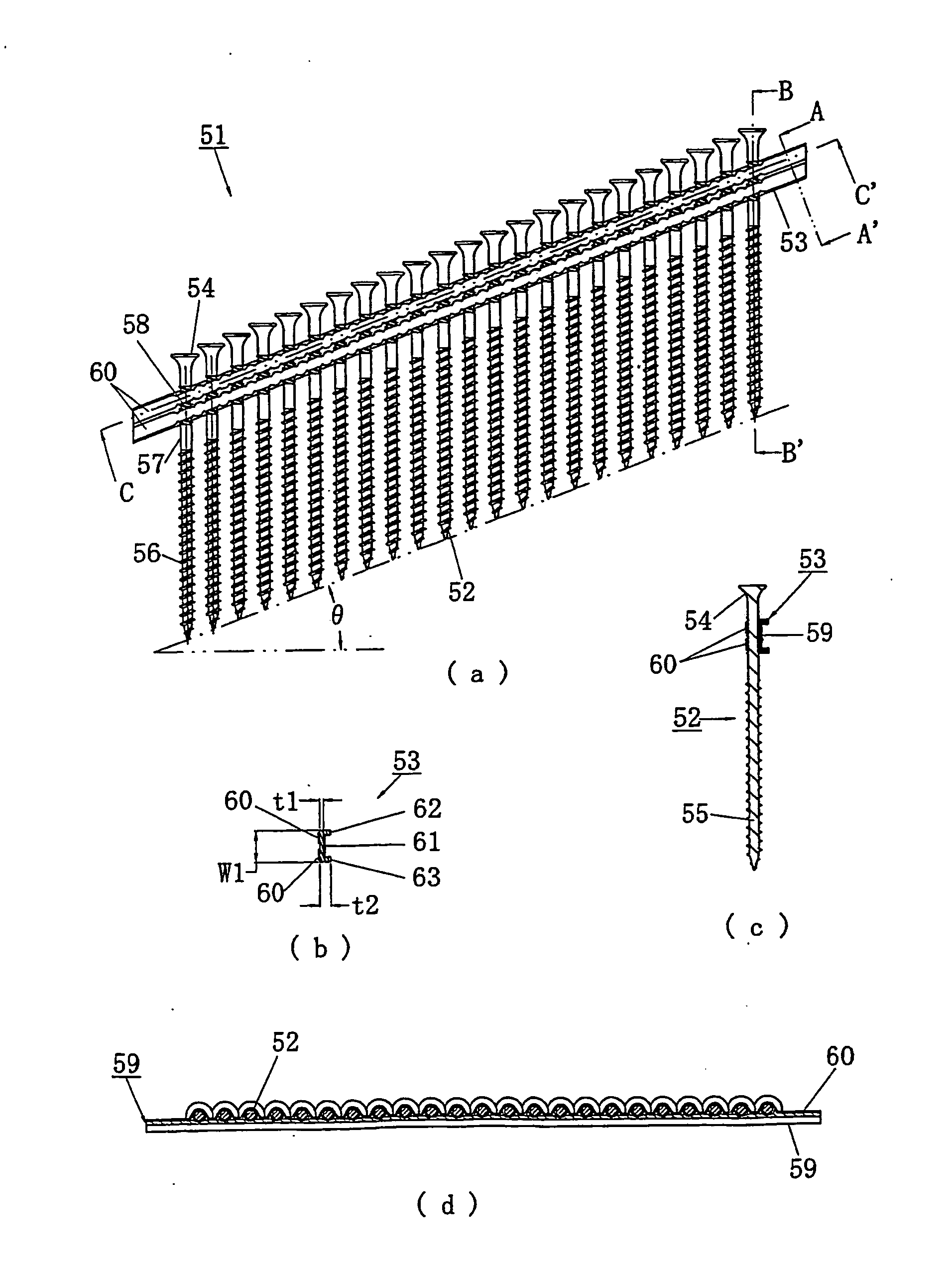

second embodiment

[0029] FIGS. 4 to 6 show the In stead of the configuration for constantly controlling the horizontal width of the connecting fastener by increasing or reducing the thickness of the connecting band, the thickness of the connecting band is provided constantly and the connecting fastener is pressed and supported by a pressing plate 22 provided in a fastener magazine 21. FIGS. 4(a), (b) show the fastener magazine 21, wherein the pressing plate 22 of a spring pressurizing type faces a feed pawl 23 in the fastener passage. The fastener passage has a wide width such that a thick fastener can be loaded as well, and the pressing plate 22 presses the connecting band of the connecting fastener so as to thrust the same against the wall surface on the feed pawl 23 side.

[0030] Connecting fasteners 31a, 31b shown in FIGS. 5(a), (b) have an angle-shaped cross sectional shape provided with a rib 33 projecting from the upper end part of the connecting bands 32a, 32b toward the direction of the press...

third embodiment

[0032] Next, a third embodiment will be explained with reference to FIGS. 7 to 10. FIG. 7(a) is a right side view of the connecting fastener, FIG. 7(b) is a cross sectional view taken along the line A-A′ in the above-mentioned right side view, FIG. 7(c) is a cross sectional view taken along the line B-B′, and FIG. 7(d) is a cross sectional view taken along the line C-C′.

[0033] The numeral 51 shows a connecting fastener according to this embodiment, with a plurality of screws 52 used as the fasteners bound by a connecting band 53. Like the above-mentioned embodiment, the connecting fastener is to be used for an fastener machine of an impact driver type. A screw 52 is substantially the same as that of the above-mentioned embodiment. The screw 52 comprises a head part 54 having a cross-shaped concavity part (not shown) on the upper end surface to be engaged with the driver bit, and a shank 55 having a screw thread formed on the outer circumference. Moreover, in the shank 55, a screw th...

fourth embodiment

[0052] Next, a fourth embodiment according to the connecting fastener will be explained with reference to FIG. 11(a).

[0053] Although the principal structure is same as the above-mentioned embodiments, the connecting band 70 used in this embodiment differs from the above-mentioned examples in the following points. That is, in the rib 71 of the connecting band 70, there is provided a concavity part 73 corresponding to the supporting portions of the screw 72. Thereby, the rib 71 can easily be deformed so that the passage of the head part of the screw 72 is facilitated, and thus the screwing operation of the screw 72 is not prevented.


PUM


Abstract

The object of the invention is to make it possible to fill connecting fasteners of various thicknesses in a single kind of fastener magazine. A connecting fastener is such that the thickness of a connecting band (13a, 13b) is increased or decreased according to the stem diameter of a screw (12a, 12b), whereby the width of the connecting fastener (11a, 11b) as seen in the direction of travel thereof is made constant, and the connecting band (13a, 13b) is brought into engagement with a longitudinal guide groove (5a) formed in the fastener passageway of the fastener magazine (5) of a screw fastening machine. This makes it possible to stably hold the connecting fasteners (11a, 11b) of various stem diameters at a given height, thus improving the versatility of the fastener magazine.

Description

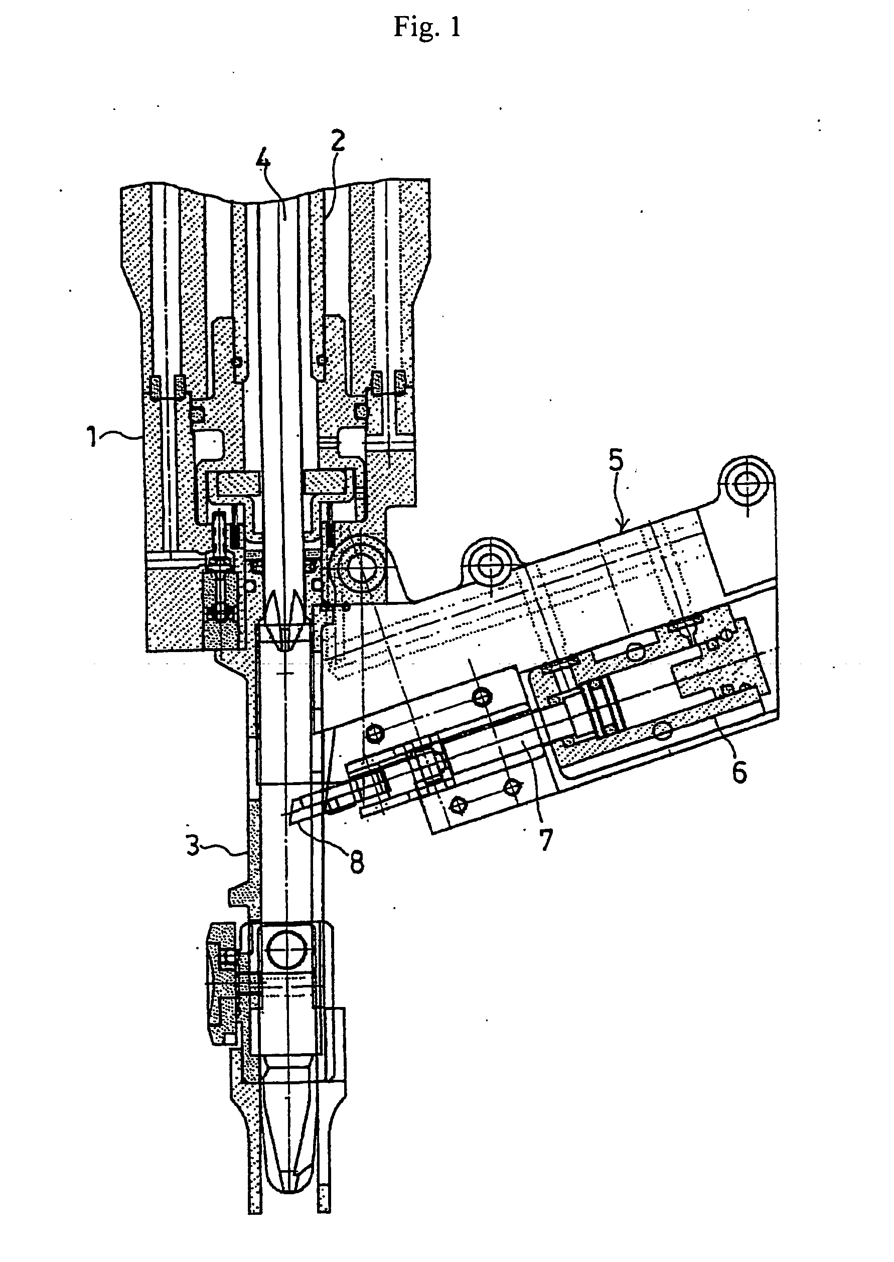
TECHNICAL FIELD [0001] The present invention relates to a connecting fastener having a plurality of screws or nails attached in parallel on a sheet or a belt of a resin, a paper, or the like. In particular, it relates to a connecting fastener capable of loading fasteners of various kinds of sizes to one kind of the fastener magazine. BACKGROUND ART [0002] There is a screw fastening machine and a nail driving machine using a connecting fastener with a plurality of fasteners such as screws and nails disposed in parallel and connected on a sheet as is well known. According to this kind of the fastening machine, a fastener magazine is attached on the rear surface of a nose so that the connecting fasteners loaded in the fastener magazine are supplied successively into the nose per one cycle operation by a feed pawl of a fastener feeding mechanism interlocked with the lifting and lowering operation of the driver in order to continuously fasten the screws or drive the nails. The cross sect...

Claims


Application Information

Patent Timeline
IPC IPC(8): F16B15/08F16B27/00
CPCF16B27/00F16B15/08
Inventor FUJIYAMA, TAKEOTAMURA, JUNICHIKANEKO, YOSHIHIROMACHIDA, MITSUHISAKOHAMA, KOICHI
Owner MAX CO LTD
Why Eureka
Eureka Blog
Learn More