Image enlarging apparatus and method

a technology of image enlargement and enlarging apparatus, which is applied in the direction of color television details, television system details, television systems, etc., can solve the problems and achieve the effect of reducing overall image quality and image resolution

Inactive Publication Date: 2005-03-03
PANASONIC CORP
View PDF6 Cites 21 Cited by
  • Summary
  • Abstract
  • Description
  • Claims
  • Application Information

AI Technical Summary

Benefits of technology

[0021] With the conventional configuration described above the vertical image signal processing circuit 206 and horizontal image signal processing circuit 207 compress the vertical and horizontal line counts of the image, and the compressed image is then enlarged by the image size adjusting circuit 210. This enlarging process degrades the image resolution (particularly the vertical resolution), and thus reduces overall image quality.
[0022] The present invention is directed to solving this problem, and an object of the invention is to provide an image enlarging apparatus and method providing a n instantaneous image enlargement function with little image degradation.
[0024] Thus comprised, the image enlarging apparatus and method of this invention provides an instantaneous image zooming effect with little image quality degradation.

Problems solved by technology

This enlarging process degrades the image resolution (particularly the vertical resolution), and thus reduces overall image quality.

Method used


Image

  • Image enlarging apparatus and method
  • Image enlarging apparatus and method
  • Image enlarging apparatus and method

Examples


first embodiment

[0036] First Embodiment

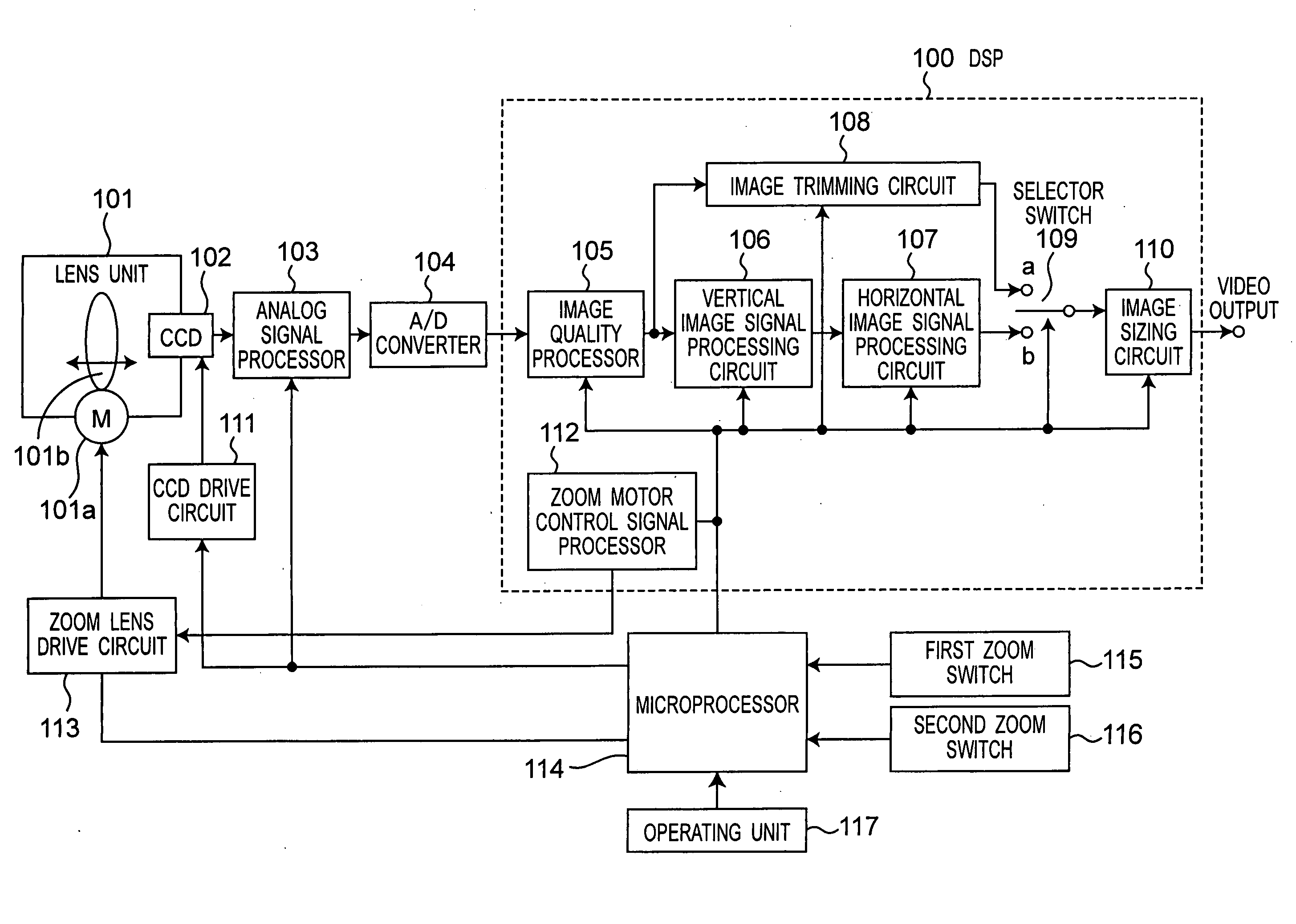
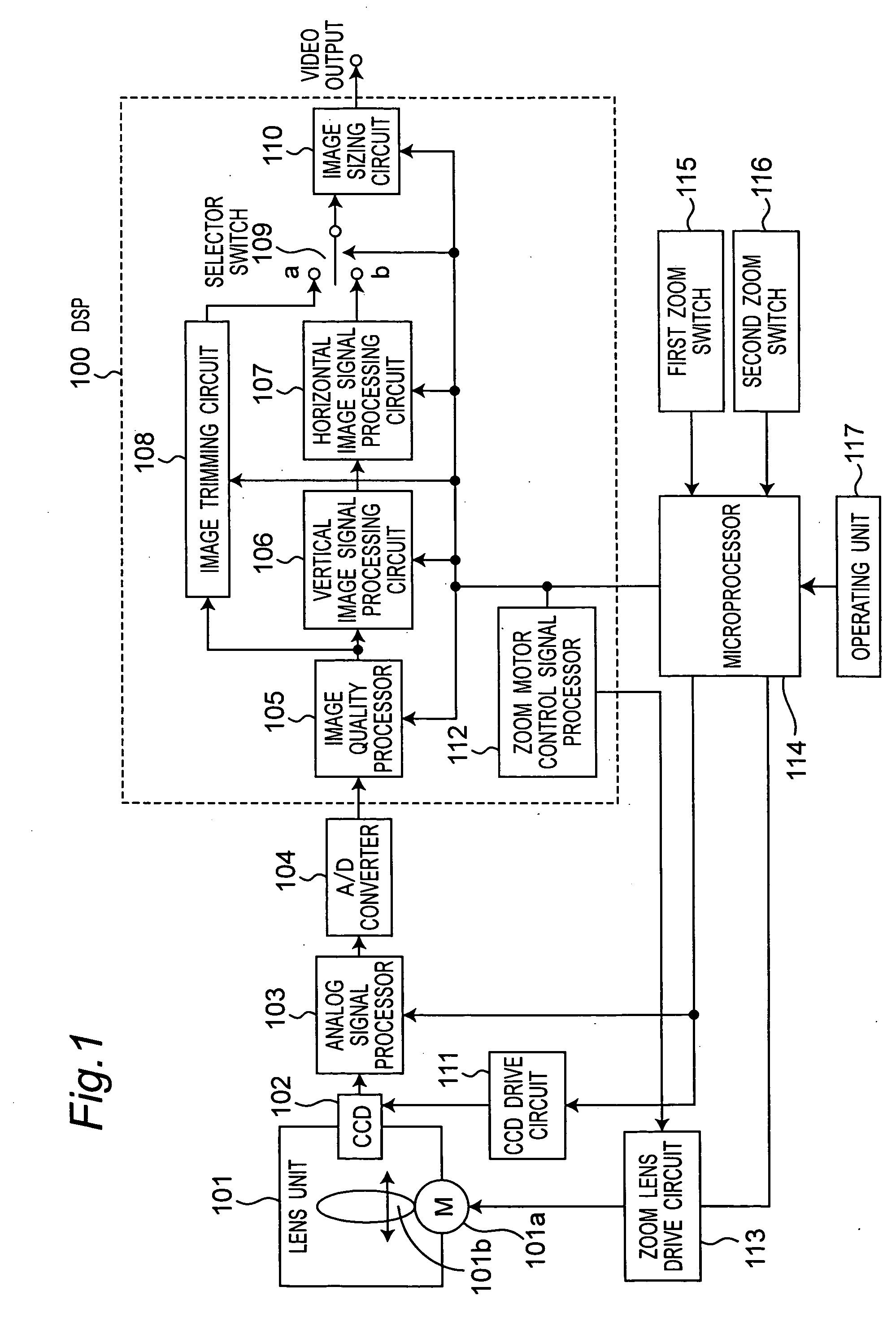
[0037]FIG. 1 is a block diagram showing the configuration of an image enlarging apparatus according to a preferred embodiment of the invention. Referring to FIG. 1, the lens unit 101 has a zoom lens 101b for optically enlarging or reducing a subject image, and a zoom motor 101a for moving the zoom lens 101b along the optical axis of the lens. The CCD 102 images and converts the incident optical signal of the subject to an electrical image signal. The analog signal processor 103 then boosts the output signal level of the image signal from the CCD 102. The A / D converter 104 then analog / digital converts the analog image signal from the analog signal processor 103 to a digital signal, and thus supplies a digital image signal to the digital signal processor (DSP) 100.

[0038] The image quality processor 105 of the DSP 100 applies gamma correction, aperture correction, or other correction process to the image signal from the A / D converter 104. The vertical image sign...


PUM


Abstract

When an image signal processing circuit first compresses the image and an image sizing circuit then enlarges the compressed image, the resolution, particularly the vertical resolution, is degraded by the enlarging process and overall image quality thus drops. This problem is solved by an image cropping circuit that crops the photographed image to a defined image area without any image compression when a second zoom switch is operated. This improves the resolution of the output image and eliminates the time needed for image compression and other signal processing operations. An enlarged image can thus be easily and immediately presented.

Description

BACKGROUND OF THE INVENTION [0001] The present invention relates to an image enlarging apparatus and an image enlarging method that can immediately produce a digital image zooming effect with little image degradation. [0002] Three of the most desirable features on the latest video cameras are a digital zoom function, high image quality, and easy operation. A conventional image enlarging system such as used in video cameras to provide a digital zoom function is described below. [0003] Conventionally, a digital zoom effect is achieved with a digital signal processing zoom circuit. The configuration of a conventional image zooming system is described below with reference to the block diagram thereof shown in FIG. 8. [0004] Referring to FIG. 8, the lens unit 201 includes a zoom lens 201b for optically enlarging and reducing images, and a zoom motor 201a for moving the zoom lens 201b along the optical axis of the lens. The CCD 202 is a charge-coupled device for imaging an incident optica...

Claims


Application Information

Patent Timeline
Patent Type & Authority Applications(United States)
IPC IPC(8): H04N5/232H04N5/262H04N5/775H04N5/781H04N5/85H04N9/804
CPCH04N5/232H04N5/23296H04N5/2628H04N9/8042H04N5/781H04N5/85H04N5/7755H04N23/635H04N23/69
Inventor MIYAZAKI, TOSHIRO
Owner PANASONIC CORP
Why Eureka
Try Eureka