Camera-assisted presentation system

a technology of camera-assisted and presentation system, which is applied in the field of camera-assisted presentation system, can solve the problems of affecting the presentation impression, and achieve the effect of improving the image display

Inactive Publication Date: 2005-03-03
ELMO CO LTD
View PDF3 Cites 12 Cited by
  • Summary
  • Abstract
  • Description
  • Claims
  • Application Information

AI Technical Summary

Benefits of technology

The object of the present invention is thus to improve display of images during an action of setting a material.

Problems solved by technology

Such omission of frames in the series of images may worsen the impression of the presentation.

Method used


Image

  • Camera-assisted presentation system
  • Camera-assisted presentation system
  • Camera-assisted presentation system

Examples


first embodiment

A. First Embodiment

(A1) Outline of Camera-Assisted Presentation System

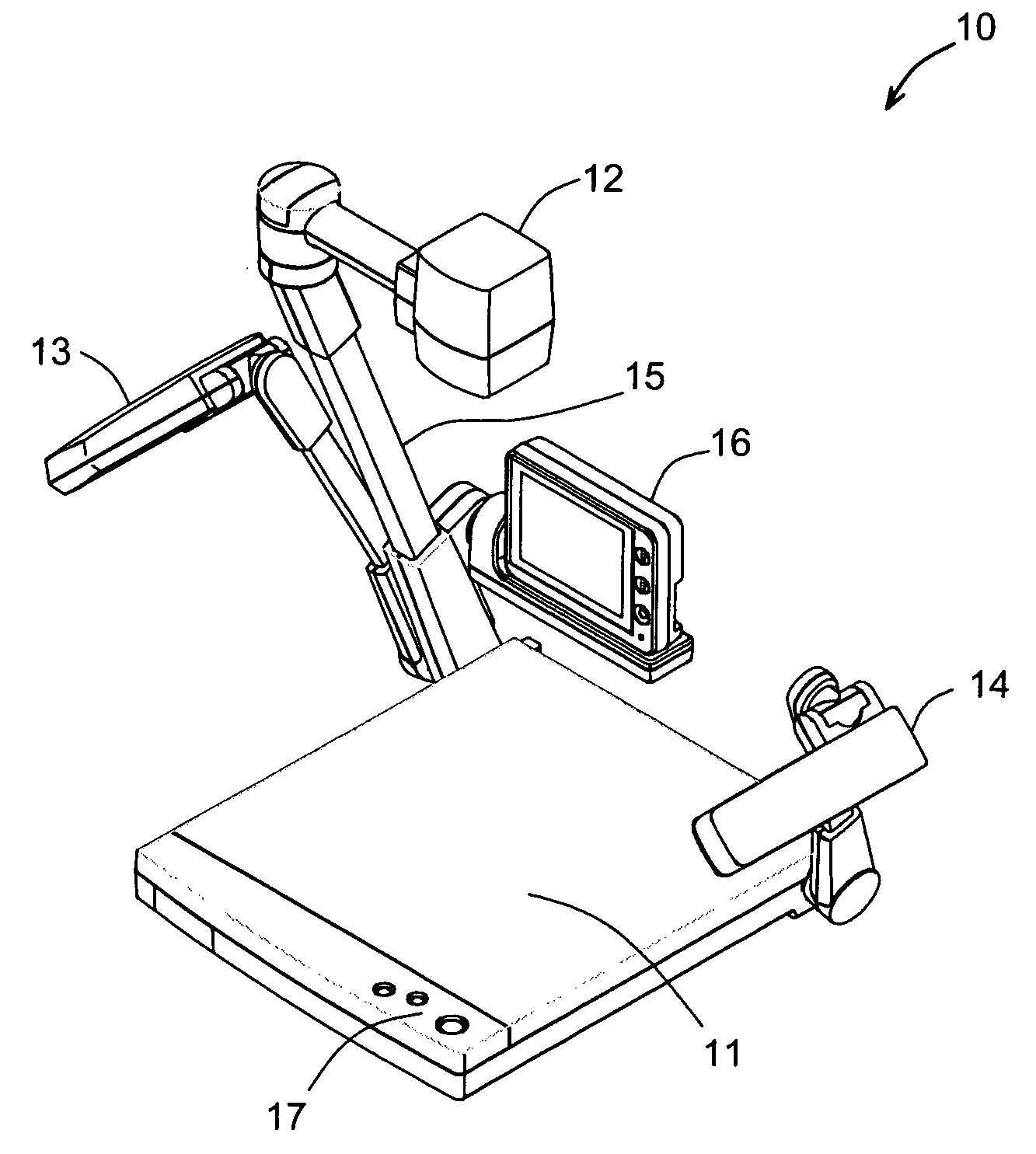
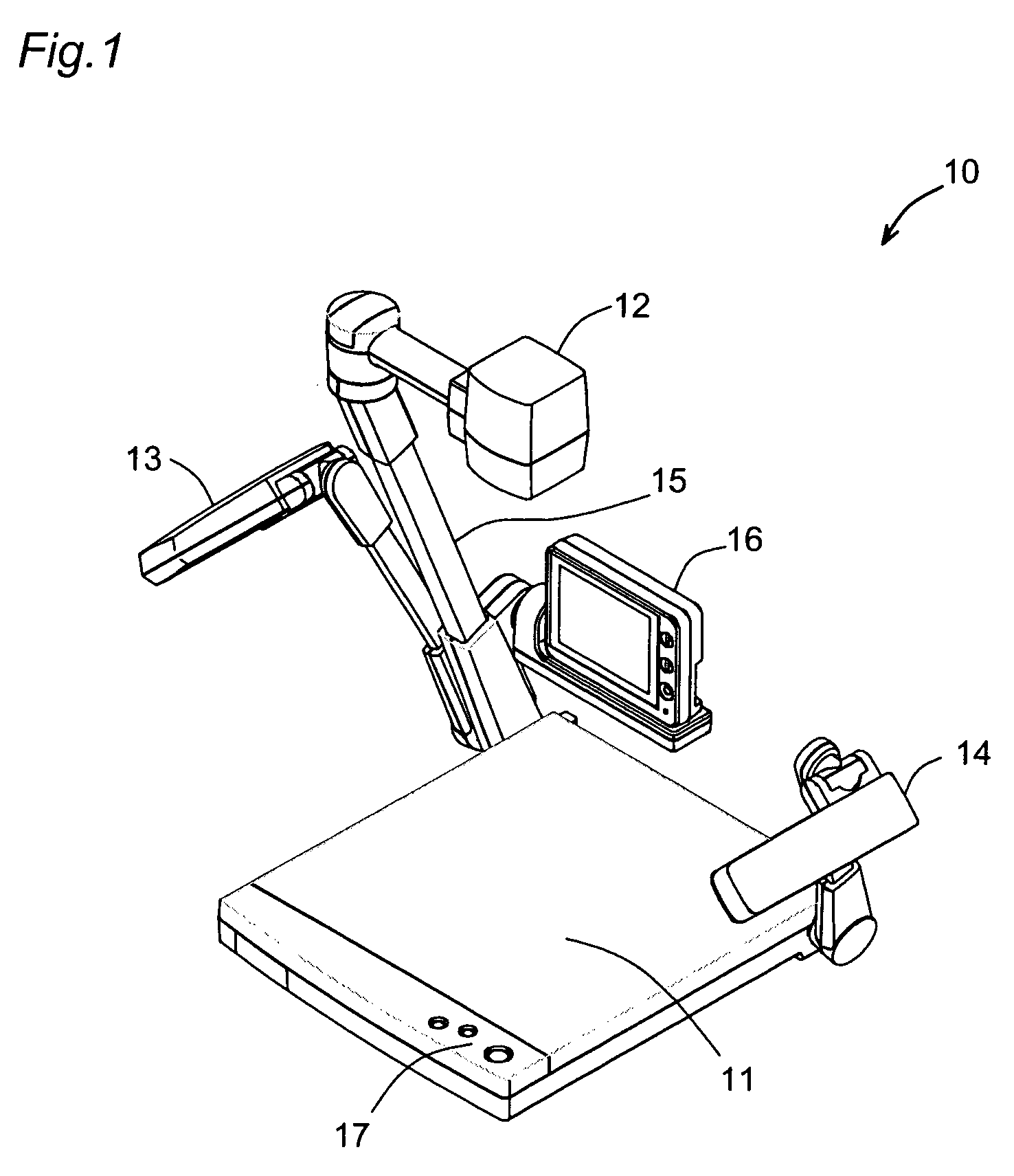
FIG. 1 is a perspective view schematically illustrating a camera-assisted presentation system 10 in a first embodiment of the present invention. The camera-assisted presentation system 10 includes a table 11 occupying most of its bottom area, a camera head 12 facing the table 11, and a pair of lamps 13 and 14 located on the left and the right sides of the table 11 to illuminate the upper surface of the table 11. Each of the lamps 13 and 14 is pivotally rotatable about the corresponding left or right rear end of the table 11 and is used to photograph an object or a material mounted on the table 11.

The camera head 12 is supported by an arm 15 to face a practically center area of the table 11 and is actuated to photograph a diversity of materials mounted on the table 11. The camera head 12 includes an auto-focusing CCD camera and has various functions relating to photographing, for example, functions of zoom and ...

second embodiment

B. Second Embodiment

(B1) Internal Structure of Camera-Assisted Presentation System

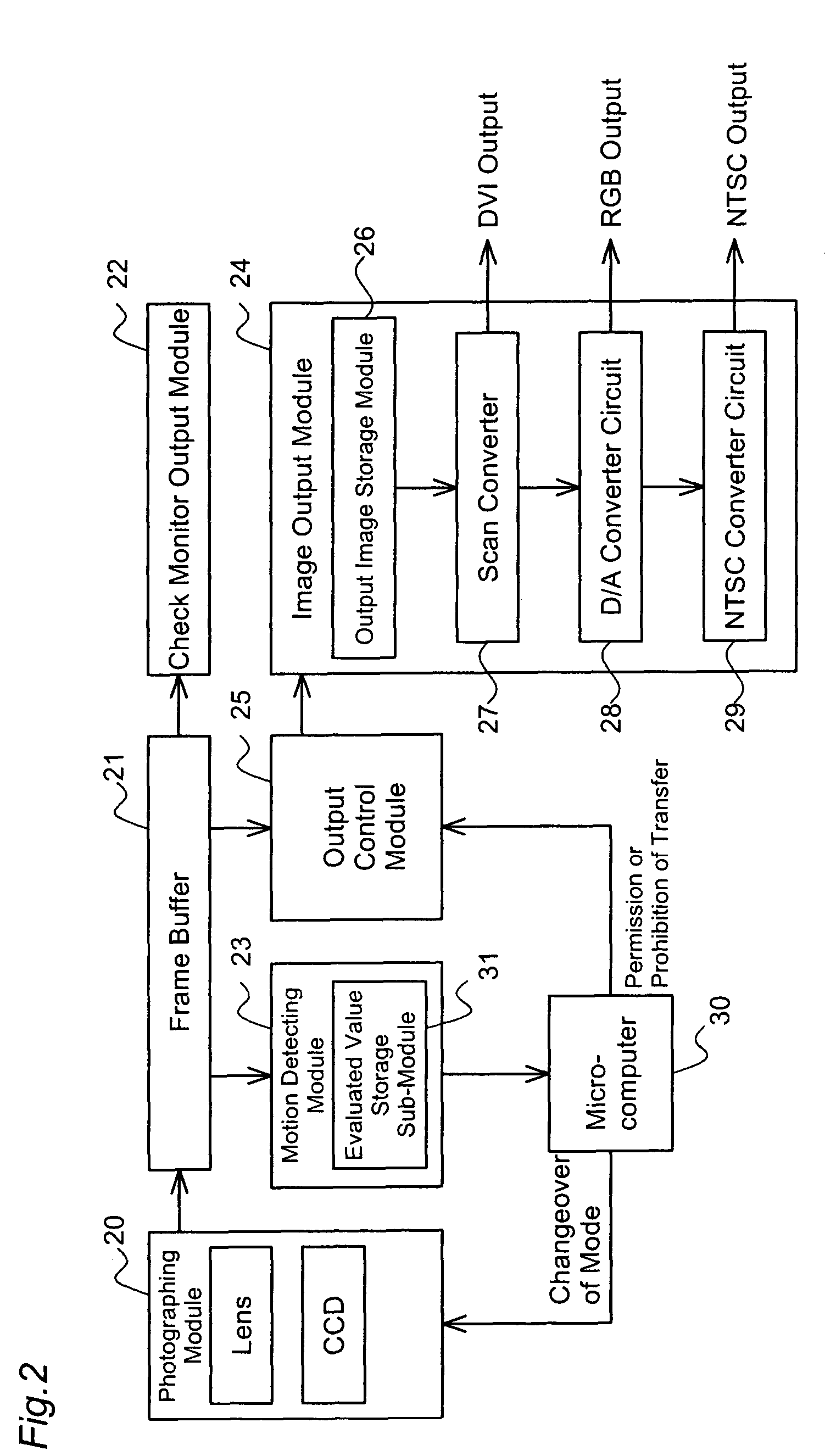
FIG. 4 is a block diagram schematically showing the internal structure of another camera-assisted presentation system 10A in a second embodiment of the present invention. The camera-assisted presentation system 10A of the second embodiment has a photographing module 40, a frame buffer 41, a check monitor output module 42, a motion detecting module 43 including an evaluated value storage sub-module 51, an image output module 44, an output control module 45, and a microcomputer 50. The image output module 44 includes an output image storage sub-module 46, a scan converter 47, a D / A converter circuit 48, and an NTSC converter circuit 49. The functions of the respective constituents in the second embodiment are substantially similar to those of the constituents of the camera-assisted presentation system 10 in the first embodiment. The difference is that the output control module 45 of the second embodime...

third embodiment

The third embodiment adopts the simple structure to prevent any image showing the setting action of the material from being undesirably displayed.

D. Modified Example

Another image output control routine is discussed below as a modified example of the first embodiment. FIG. 8 is a flowchart showing the image output control routine in the modified example of the first embodiment. The microcomputer 30 sets the photographing module 20 in the all pixels reading mode and inputs image data representing an object photographed in the all pixels reading mode into the frame buffer 21 (step S40). The motion detecting module 23 is then activated by the microcomputer 30 to detect a motion of the object (step S41). In the case of detection of a motion of the object at step S41, the microcomputer 30 controls the output control module 25 to prohibit transfer of the image data (step S42). In the case of detection of no motion of the object at step S41, on the other hand, the microcomputer 30 cancel...


PUM


Abstract

In a camera-assisted presentation system, a microcomputer activates a motion detecting module to detect a motion of an object, based on a variation in luminance of image data representing a material photographed by a photographing module. In the case of detection of a motion of the object, the microcomputer controls an output control module to prohibit transfer of the image data to an image output module. Image data photographed immediately before detection of the motion is kept in an output image storage sub-module of the image output module. This arrangement effectively prevents any action of setting the material from being undesirably displayed on an external display unit, thus ensuring smooth presentation with improved display of images during the actions of setting the material in the camera-assisted presentation system.

Description

BACKGROUND OF THE INVENTION 1. Field of the Invention The present invention relates to a camera-assisted presentation system that causes photographed images of materials to be displayed on a display unit. 2. Description of the Related Art Camera-assisted presentation systems have been known and widely used for the purpose of education and presentation. The systems photograph materials and samples to make photographed images displayed on a display unit, such as a monitor or a projector. With the recent advancement of the camera technology, some of the camera-assisted presentation systems have the high resolution and are capable of outputting images of more than 1 million pixels. The conventional camera-assisted presentation systems, however, also display the user's actions of setting the material on a display unit. In the case of displaying such actions, with the enhanced resolution of a camera built in the camera-assisted presentation system, some frames may be omitted due to a...

Claims


Application Information

Patent Timeline
Patent Type & Authority Applications(United States)
IPC IPC(8): H04N5/222H04N7/18
CPCY10S353/03H04N7/183
Inventor MORI, ISAOTANABE, MASAKIMIZUMOTO, RYUICHI
Owner ELMO CO LTD
Why Eureka
Try Eureka