Grommet-mounting structure and grommet

a technology of mounting structure and grommet, which is applied in the direction of manufacturing tools, building scaffolds, transportation and packaging, etc., can solve the problems of shitting the fixed position of the tubular portion, cutting the wire harness within the tubular portion, etc., and achieve the effect of preventing the biting from being held

Inactive Publication Date: 2005-03-03
YAZAKI CORP
View PDF10 Cites 3 Cited by
  • Summary
  • Abstract
  • Description
  • Claims
  • Application Information

AI Technical Summary

Benefits of technology

[0030] The present invention solves a problem (as encountered with the related structure) that when the trunk lid or the like is repeatedly opened and closed, the band is displaced in the axial direction of the tubular portion, and the fixed position of the tubular portion shifts, so that the tubular portion is bitten by the trunk lid when the trunk lid is closed. Therefor

Problems solved by technology

When the flexible tubular portion of the grommet is freely deformed during the opening and closing of the trunk lid, there is a fear that the wire harness is bitten by the trunk lid when the trunk lid is closed, so that the wire harness within this tubular portion is cut.
In the above related grommet-mounting structure, however, the band-attaching portion

Method used


Image

  • Grommet-mounting structure and grommet
  • Grommet-mounting structure and grommet
  • Grommet-mounting structure and grommet

Examples


Embodiment Construction

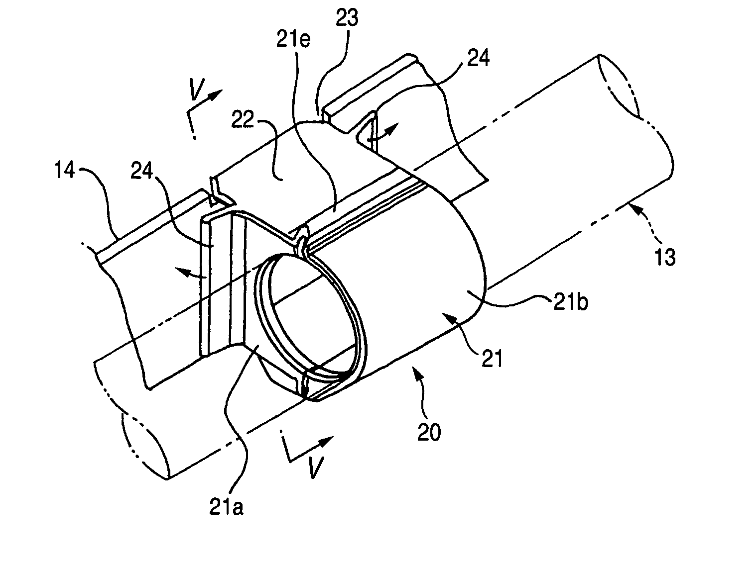
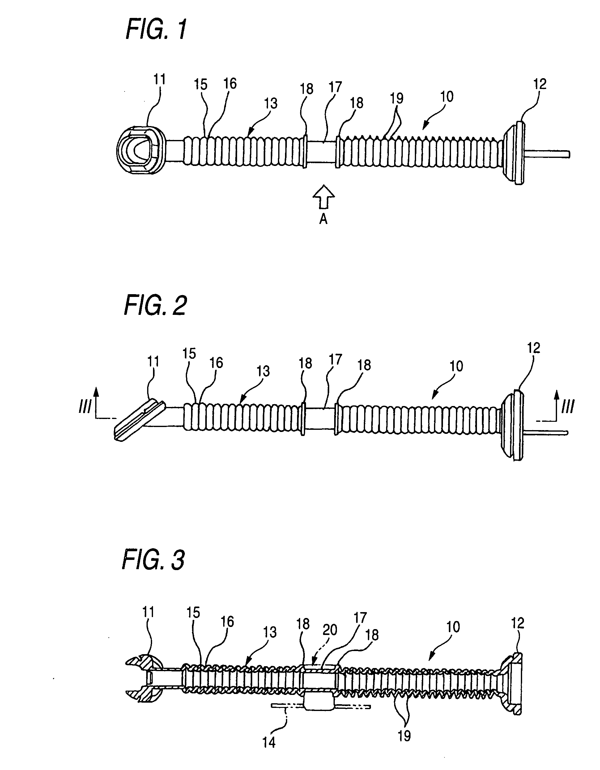
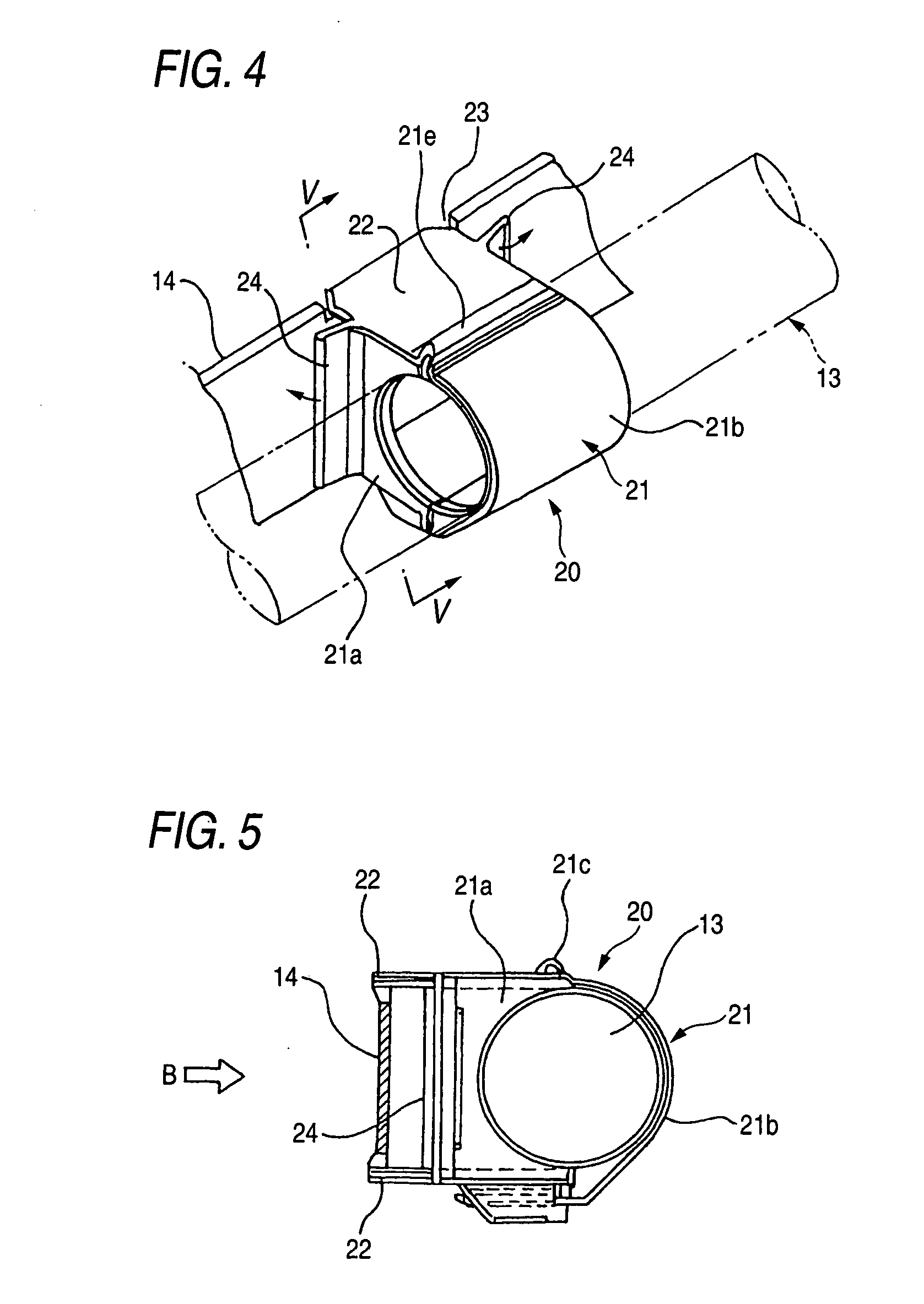
[0040] A preferred embodiment of the present invention will now be described in detail with reference to the drawings. FIG. 1 is a view showing one preferred embodiment of a grommet of the invention, FIG. 2 is a view as seen from a direction of arrow A of FIG. 1, FIG. 3 is a cross-sectional view taken along the line III-III of FIG. 2, FIG. 4 is a perspective view showing the whole of a clip, FIG. 5 is a cross-sectional view taken along the line V-V of FIG. 4, FIG. 6 is a view as seen from a direction of arrow B of FIG. 5, FIG. 7 is a view showing modified step portions, and FIG. 8 is a view showing a modified thickened portion of a tubular portion.

[0041] As shown in FIGS. 1 to 3, the grommet 10 (embodying the invention) for the passage of a wire harness (not shown) (which is installed between a vehicle body (not shown), serving as a first member, and a trunk lid (not shown) which serves as a second member, and can be opened and closed relative to the vehicle body through a link mec...


PUM


Abstract

A structure of mounting a grommet, includes a first member, a second member, a link mechanism which connects the first member and the second member so that the first member and the second member are movable toward and away from each other, a grommet which is arranged between the first member and the second member. The grommet includes a first fixing portion fixed to the first member, a second fixing portion fixed to the second member, a flexible tubular portion extending between the first fixing portion and the second fixing portion, and an attaching portion provided on the tubular portion. A grip member grips the attaching portion. The tubular portion is fixed to at least one of the link mechanism, the first member and the second member through the grip member.

Description

BACKGROUND OF THE INVENTION [0001] This invention relates to a structure of mounting a grommet for the passage of a wire harness (installed, for example, in an automobile or the like) therethrough so as to protect it, and also relates to this grommet. [0002] Generally, one example of those members which are opened and closed relative to a vehicle body (first member) through a link mechanism is a trunk lid (second member). In addition to tail lamps, a license plate lamp and a high-mount stop lamp, a wiper is mounted on the trunk lid in some kinds of cars as in a hatch back-type car. Therefore, it is necessary to install a wire harness between the vehicle body and the trunk lid so as to supply electric power to these parts. [0003] This wire harness is passed through the bore of a grommet, and is protected by this grommet, the grommet including a first fixing portion of an annular shape for being fixed to the vehicle body, a second fixing portion of an annular shape for being fixed to ...

Claims


Application Information

Patent Timeline
IPC IPC(8): H02G3/04B60R16/02H02G3/22
CPCY10T403/71B60R16/0222
Inventor SANTANDA, TSUTOMUOGAWA, TATSUO
Owner YAZAKI CORP
Why Eureka
Try Eureka