Plug connector, receptacle connector, and joint-type connector

a technology of receptacle and connector, which is applied in the direction of coupling device connection, coupling protective earth/shielding arrangement, electric discharge lamps, etc., can solve the problems of increasing device size and production cost, and achieve the effect of compact device, reduced mounting space inside the device, and reduced the number of necessary connectors

Inactive Publication Date: 2005-03-03
SUZUKI MITSUO +2
View PDF0 Cites 67 Cited by
  • Summary
  • Abstract
  • Description
  • Claims
  • Application Information

AI Technical Summary

Benefits of technology

[0004] With the foregoing in view, it is an object of the present invention to provide a connector with a configuration making it possible to decrease the number of necessary connectors, to reduce the mounting space inside the device, to make the device compact, and to reduce the production cost.

Problems solved by technology

As a result, a mounting space was necessary at the boards of the devices for a power supply line which resulted in increased size of the device and production cost.

Method used


Image

  • Plug connector, receptacle connector, and joint-type connector
  • Plug connector, receptacle connector, and joint-type connector
  • Plug connector, receptacle connector, and joint-type connector

Examples


Embodiment Construction

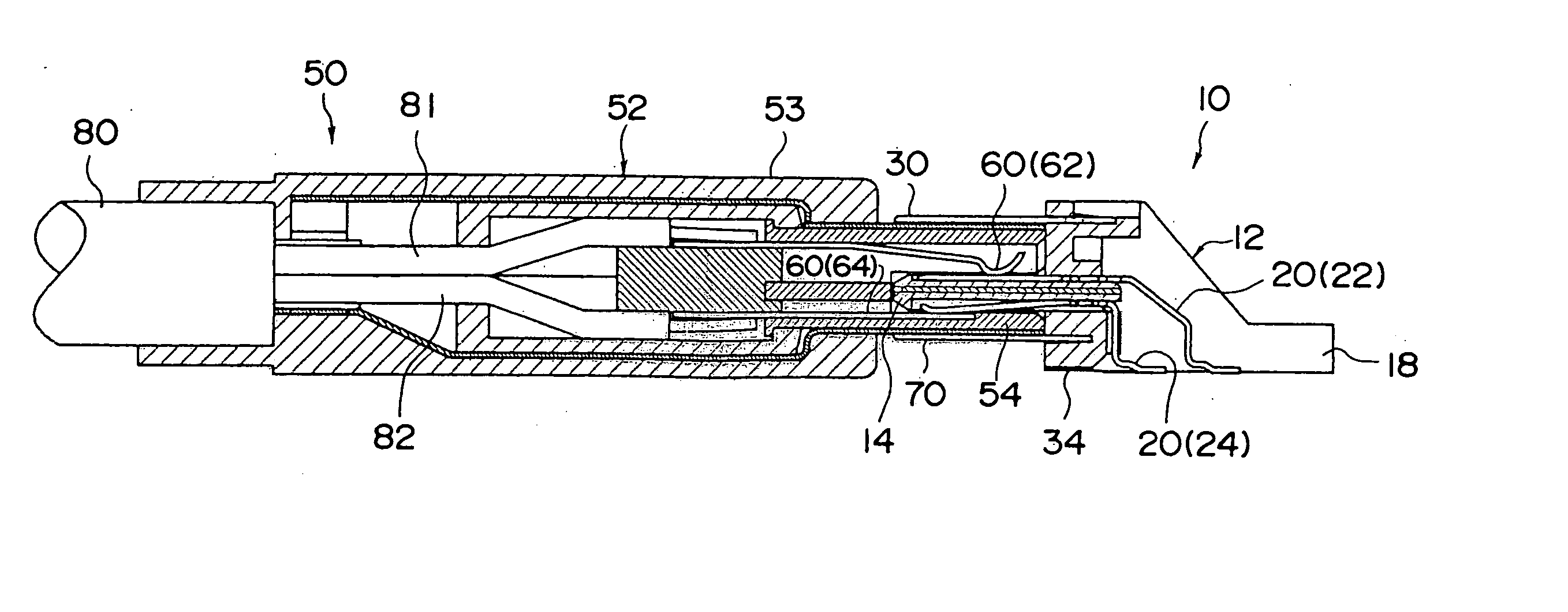
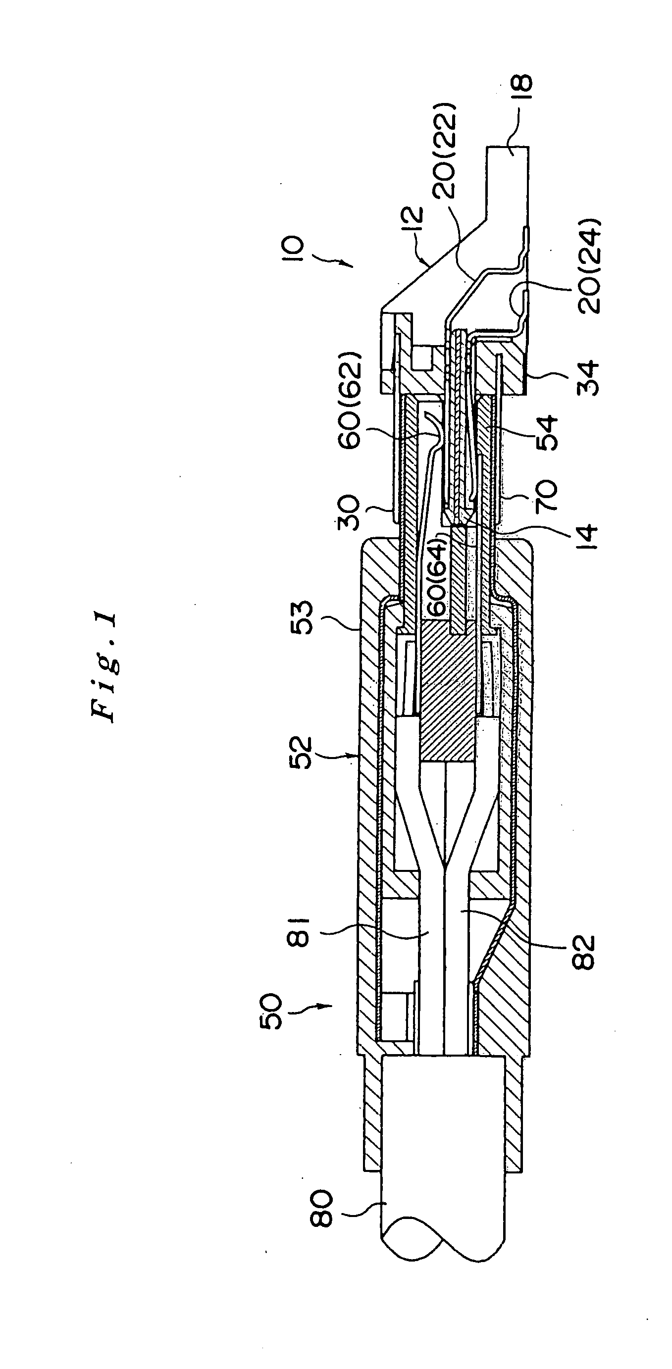
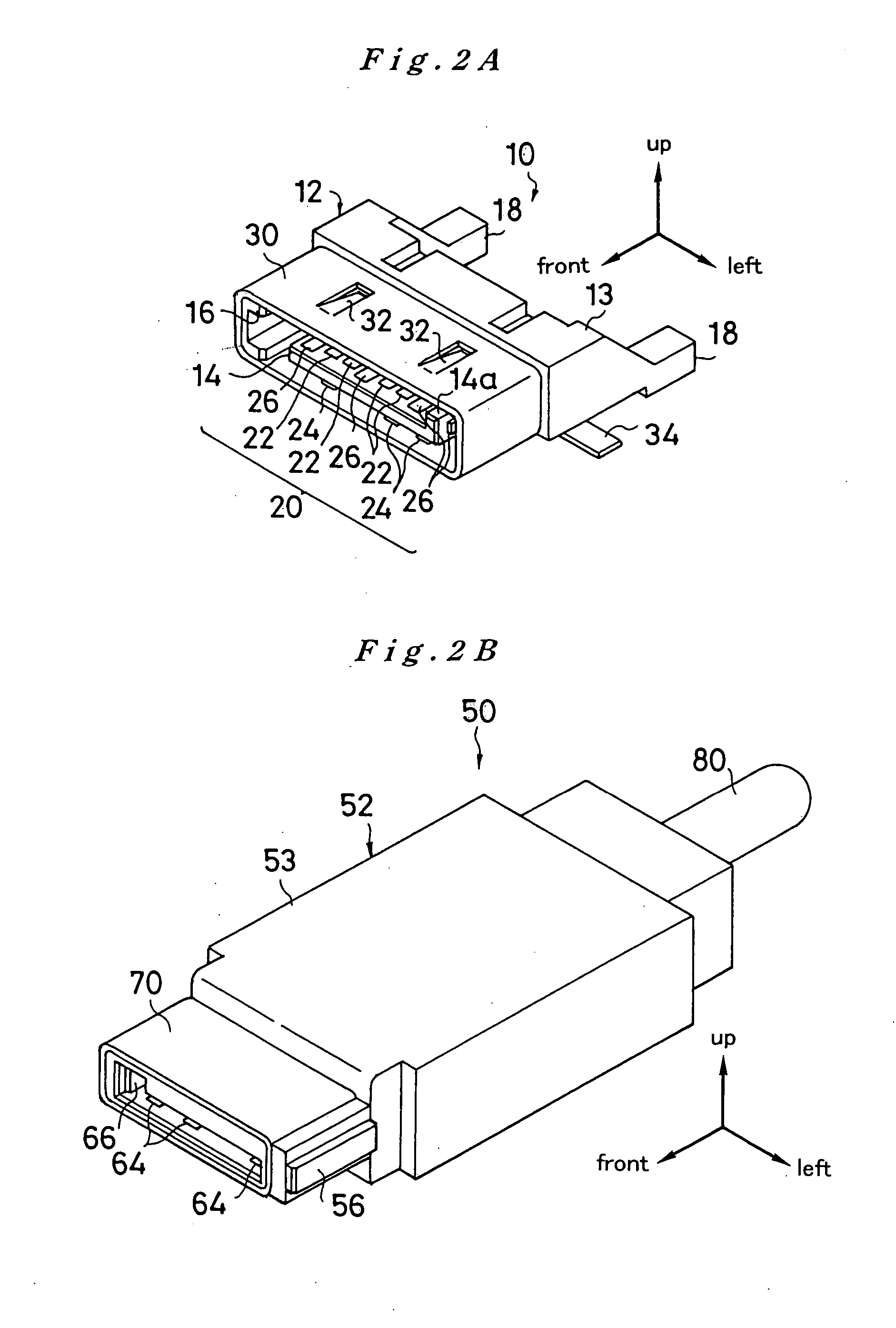
[0025] The preferred embodiments of the present invention will be described hereinbelow with reference to the appended drawings. FIG. 2 is a joint-type connector of the present invention. FIG. 2A shows a plug connector 10 (corresponds to the plug connector in accordance with the present invention) constituting the joint-type connector, and FIG. 2B shows a receptacle connector 50 (corresponds to the receptacle connector in accordance with the present invention) used for joining to the plug connector 10. In the present embodiment, for convenience of explanation, the front-rear, left-right, and up-down directions for the plug connector 10 and receptacle connector 50 are defined as shown in the figure.

[0026] First, the plug connector 10 will be described by combining FIG. 3 with FIG. 2A. The plug connector 10 is based on a well-known plug connector conforming to a serial ATA standard (more specifically, it is a plug connector conforming to a serial ATA standard equipped with the below-...


PUM


Abstract

A plug connector, comprising a housing 12 comprising a flat plug portion 14 extending in the left-right direction for insertion into a plug accommodation space 54a of a housing 52 of a receptacle connector 50 serving as a joining mate, and a signal contact 22 provided at the upper surface of the plug portion 14 and connected to a signal line (signal terminal on a board), the configuration of the plug connector being such that the signal contact 22 is brought into contact with a signal contact 62 of the mating connector in a state where the housing 12 has been joined to mating housing 52, wherein a power source contact 24 for connection to a power source line (power source terminal on a board) is provided at the lower surface of the plug portion 14.

Description

FIELD OF THE INVENTION [0001] The present invention relates to a plug connector, a receptacle connector, and a joint-type connector used for connecting devices, such as personal computers or peripheral devices, with a signal cable conducting signal transmission between those devices. BACKGROUND OF THE INVENTION [0002] Main boards of personal computers and internal hard disks, or main boards and peripheral devices (for example, external memory devices such as CD-ROM drives and DVD-ROM drives) are connected by signal cables conducting signal transmission between those devices, and the signal cable and the device are connected via a connector comprising a housing that can be joined to both of them. Replaceability of the connectors is ensured by standardization of the connector shape, and the corresponding contacts are brought into contact by joining the mating connector and the housing to each other. For example, a USB standard and a serial ATA standard (See Internet [search as of Aug....

Claims


Application Information

Patent Timeline
Patent Type & Authority Applications(United States)
IPC IPC(8): H01R13/46H01R13/648H01R24/00
CPCH01R9/032H01R13/64H01R24/60H01R23/688H01R2107/00H01R13/65802H01R13/6582H01R13/65912
Inventor SUZUKI, MITSUOKUSUDA, NOBUYUKISAKAI, SADAAKI
Owner SUZUKI MITSUO
Why Eureka
Try Eureka