
Method and apparatus for relay facilitated communications

a relay and communication technology, applied in the field of wireless communication, can solve the problems of inability of otherwise in-range remote communication units to achieve the desired level of service without a concurrent significant increase in transmission power, and achieve the effect of facilitating communication without affecting the quality of service of the desired level of servi

Inactive Publication Date: 2005-03-03
GOOGLE TECH HLDG LLC
View PDF12 Cites 185 Cited by
  • Summary
  • Abstract
  • Description
  • Claims
  • Application Information

AI Technical Summary

Problems solved by technology

Unfortunately, despite various improvements to both systems and remote communication units, there remain times and circumstances when the transmissions of a communication unit that is within the communication range of a given communication system are nevertheless not received reliably at a given desired level of quality of service.
Various causes exist for this result, including but not limited to shadow fading and other propagation issues.
For example, as data transmission rates demands continue to increase (leading frequently to a corresponding increase in bandwidth), the ability of an otherwise in-range remote communication unit to successfully effect a desired level of service without a concurrent significant increase in transmission power usually becomes impaired.

Method used


Image

  • Method and apparatus for relay facilitated communications
  • Method and apparatus for relay facilitated communications
  • Method and apparatus for relay facilitated communications

Examples


example 1

Referring now to FIG. 6, a remote unit that is within reception range of a given base site transmits an access request 61. The base site determines that a relay resource should be allocated to adequately support the quality of service needs of the requested communication and provides corresponding instructions 62 to a selected relay resource. The base site then conveys a grant 63 to the remote unit containing, for example, information identifying the bearer channel and the like. The remote unit then wirelessly transmits its bearer data 64. The relay resource receives this bearer data transmission 64 and concurrently relays 65 this transmission to the base site (using, for example, a wireline pathway to the base site).

example 2

Referring now to FIG. 7, the same sequence of events as was set forth in example 1 above can be repeated until reception of the bearer data transmission 64 by the relay resource. In this example, however, the relay resource does not effect a concurrent relaying of the received transmission. Instead, the relay resource effects a store-and-forward action by retaining the received information and relaying the information at a later time (using, for example, the same or another wireless bearer channel as was used by the remote unit to convey the original transmission).

example 3

Referring now to FIG. 8, the remote unit can again issue an access request 61, in response to which the base site can properly instruct 62 the relay resource and issue a corresponding grant 63 to the remote unit. In this example, the bearer data transmission 81 from the remote unit is conveyed to and received by the base site. In addition, the bearer data transmission is also received by the relay resource, which then effects a store-and-forward relaying 82 of that transmission to the base site. So configured, the base site has both transmissions to utilize in various ways as described above.


PUM


Abstract

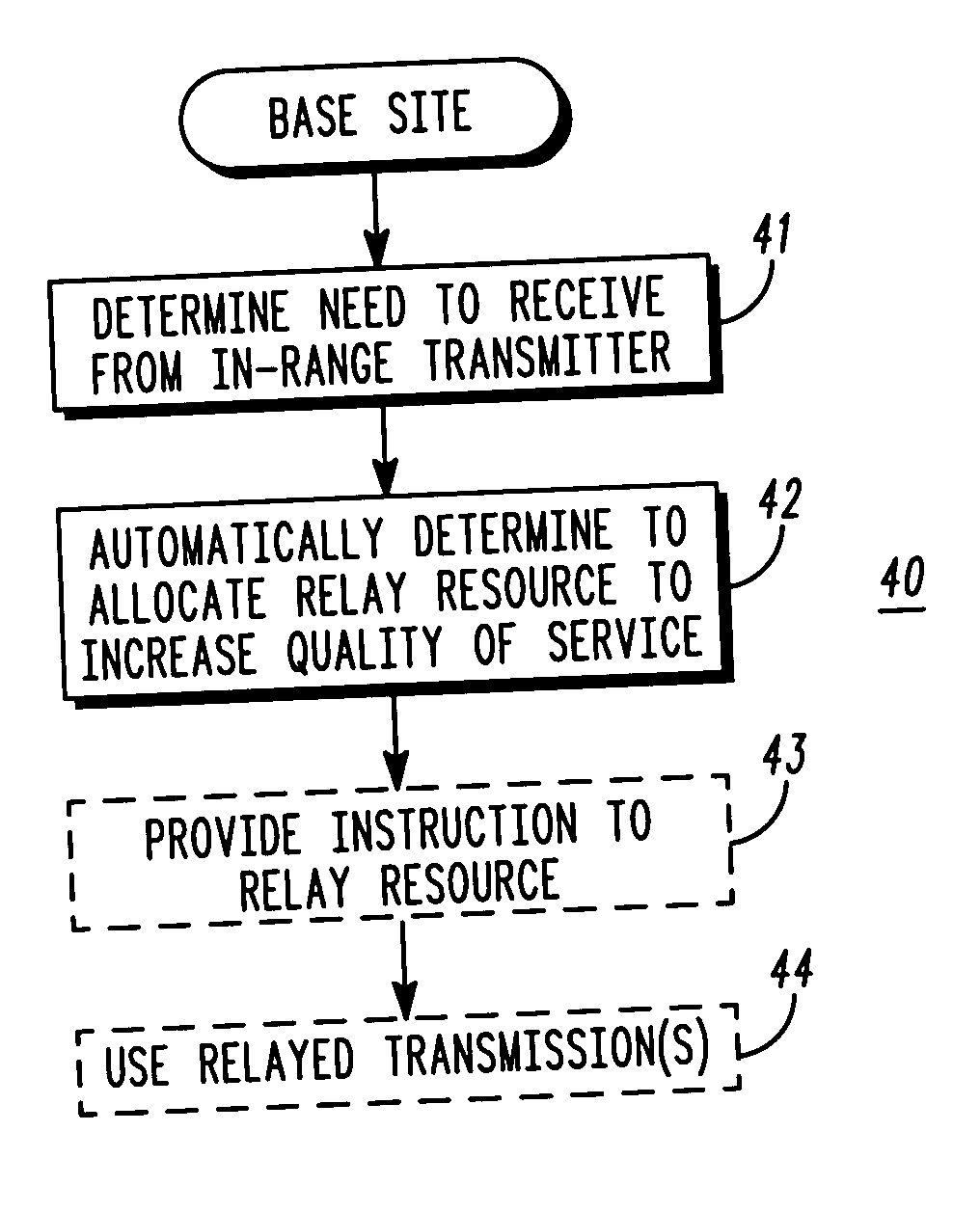
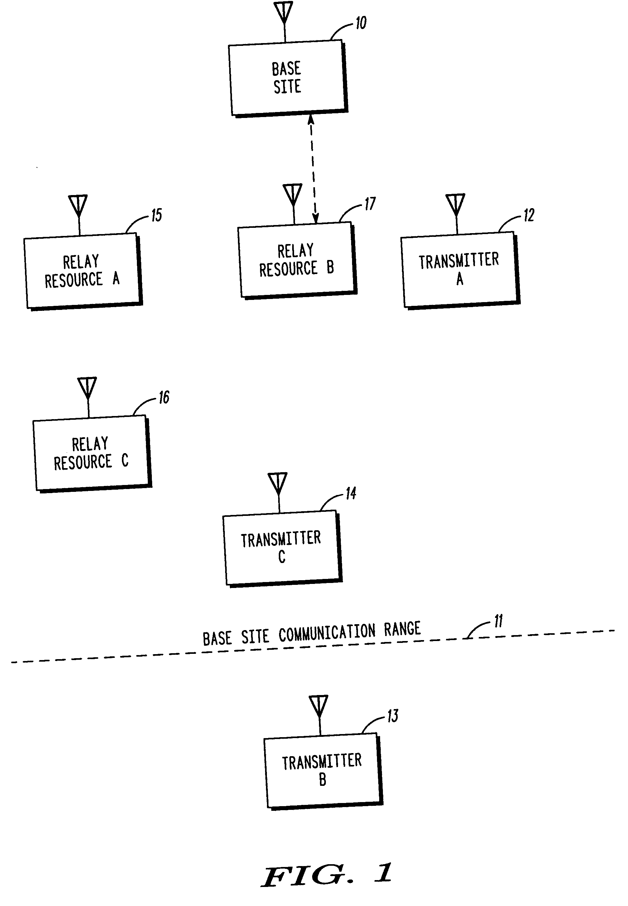
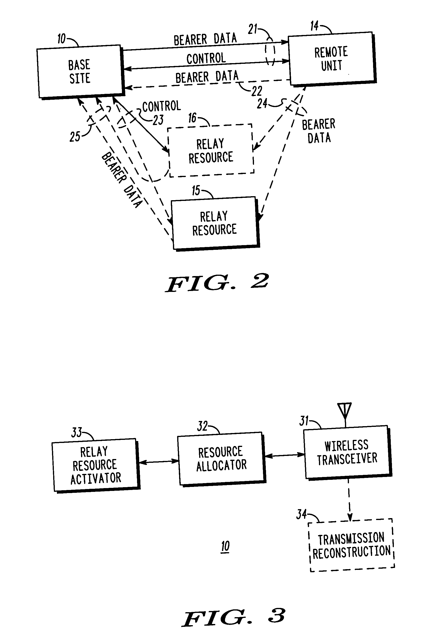
Communications sourced by a remote unit (14) that is already within reception range of a base site (10) can nevertheless be further facilitated through allocation of one or more relay resources (15, 16). Such relay resources, properly employed, then serve to effectively increase the quality of service for the facilitated communication. This, in turn, can permit the use of, for example, increased data rates for communications from a relatively low power remote unit.

Description

TECHNICAL FIELD This invention relates generally to wireless communications and more particularly to the use of communication relays. BACKGROUND Wireless communication systems are known in the art. In many such systems remote communication units (at least some of which may be mobile) communicate with one another and / or with others via system infrastructure such as fixed-location transmitters and receivers. In general, wireless communication systems are characterized by a corresponding communication range (typically characterized by either or both of a transmission range and a reception range) beyond which the wireless communications capability of the system infrastructure cannot usefully extend. Repeaters are also known in the art. Such devices typically serve to extend the communication range of a given communication system (by extending the transmission and / or reception range). Via this mechanism, for example, a relatively low power remote communication unit can effectively com...

Claims


Application Information

Patent Timeline
Patent Type & Authority Applications(United States)
IPC IPC(8): H04B7/26H04L12/56H04W16/26H04W52/00H04W72/04H04W88/04H04W88/08
CPCH04B7/15542H04B7/2606H04W16/26H04L2001/0097H04W88/04H04W88/085H04L1/1867H04W84/047H04W72/04Y02D30/70H04W88/08
Inventor SARTORI, PHILIPPE J.BAUM, KEVIN L.CLASSON, BRIAN K.CUDAK, MARKNANGIA, VIJAYVISOTSKY, EUGENE
Owner GOOGLE TECH HLDG LLC
Learn More