
Wireless connectivity module

a wireless connectivity and module technology, applied in the field of wireless technology, can solve the problems of limited oem expertise, difficult to hire the necessary talent, and difficult to achieve the effect of data exchang

Inactive Publication Date: 2005-03-03
DEV CAPITAL VENTURES
View PDF5 Cites 63 Cited by
  • Summary
  • Abstract
  • Description
  • Claims
  • Application Information

AI Technical Summary

Benefits of technology

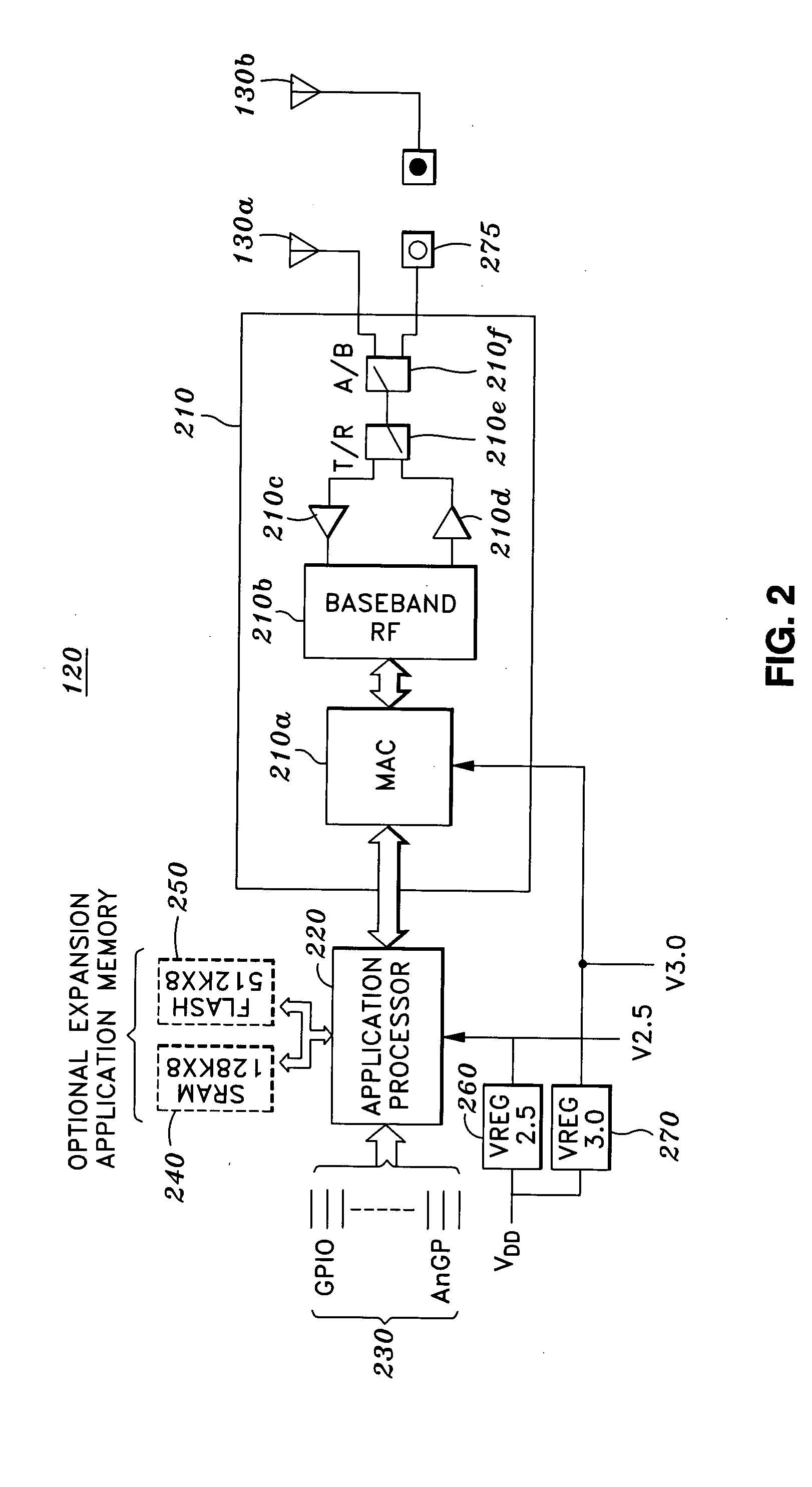
[0010] In one embodiment, the module includes a wireless radio supporting a wireless protocol, and an antenna in communication with the radio capable of transmitting and receiving wireless signals over a wireless link. Software running on an application processor of the module facilitates data exchange between a host device and the radio by converting data between a host-oriented protocol (or other appropriate protocol) and a wireless protocol, thereby providing the host device with network connectivity. Flash memory can also be provided for storing a configuration of the module.

Problems solved by technology

Unfortunately, the implementation of wireless functionality can pose a significant challenge to such OEMs.
Typically, an OEM's expertise will be limited to technological fields directly relevant to its products.
Moreover, for such an OEM, it may be cost-prohibitive to hire the necessary talent and fund the development of a device-specific wireless solution.
Ad hoc designs are unlikely to offer such compatibility,
The writing and re-writing of large amounts of software code each time the configuration changes can be a time consuming and inefficient way for OEMs, or users of their products, to update the configuration of a wireless device.

Method used


Image

  • Wireless connectivity module
  • Wireless connectivity module
  • Wireless connectivity module

Examples


Embodiment Construction

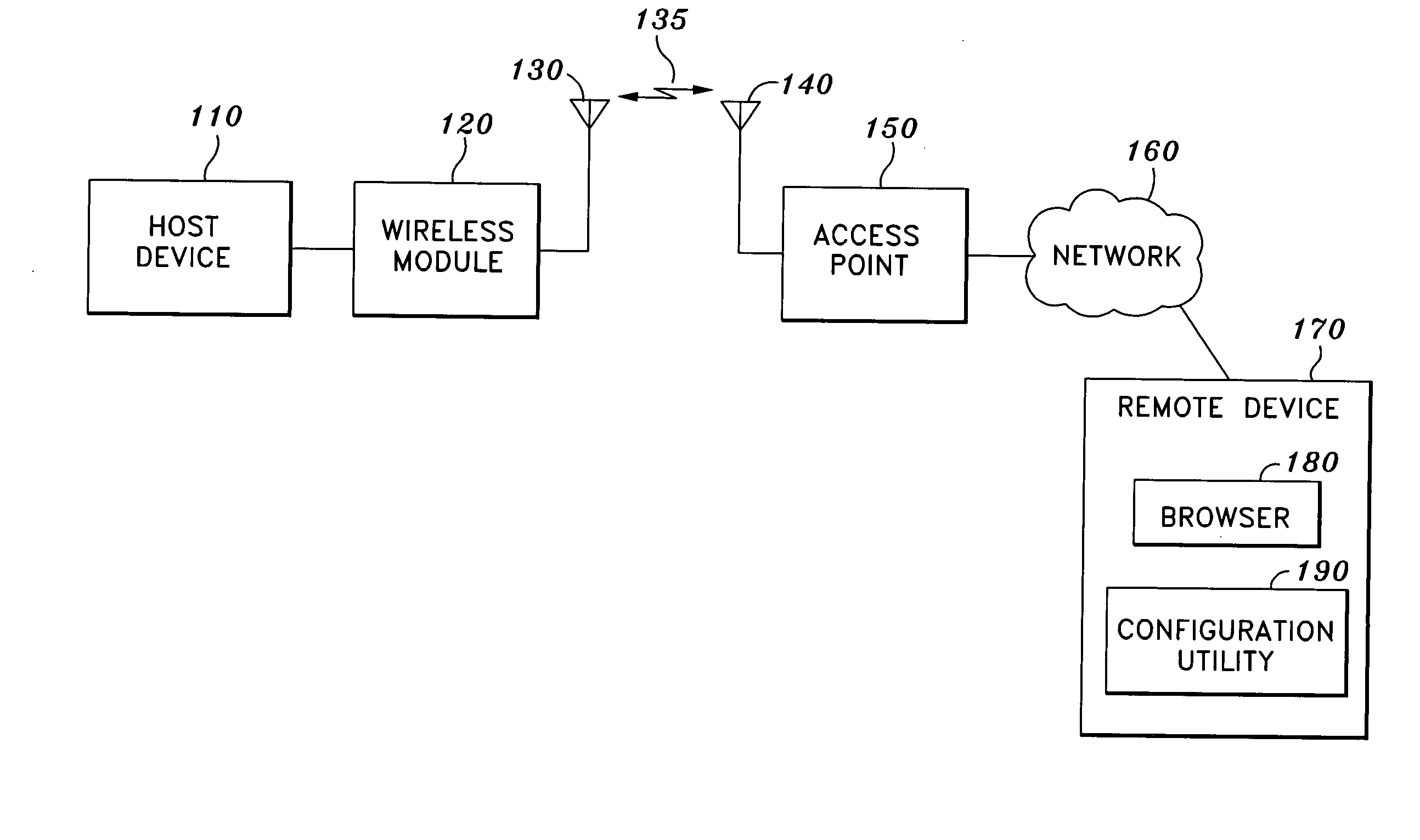
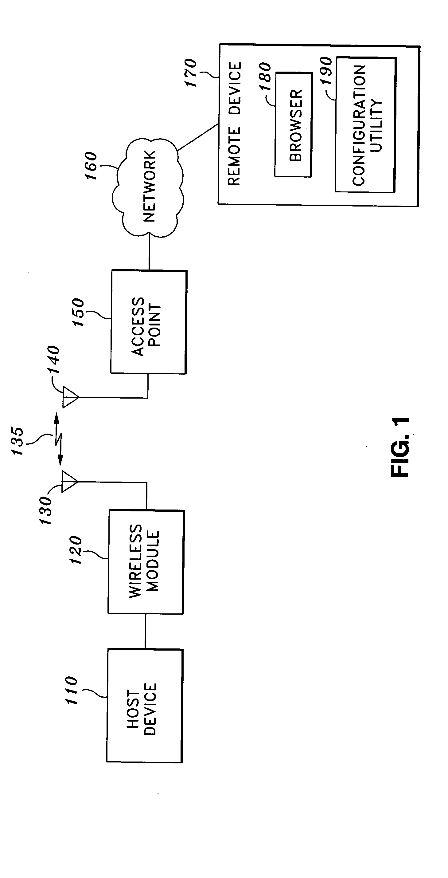
[0025]FIG. 1 is a block diagram of a system that facilitates wireless communication between a host device and a remote device in accordance with an embodiment of the present invention. The system of FIG. 1 provides a host device 110 and wireless module 120 in communication with access point 150 over wireless link 135. Access point 150 is in communication with remote device 170 over network 160. As illustrated by the connections of FIG. 1, module 120 allows for communication between host 110 and remote device 170 over wireless link 135, access point 150, and network 160.

[0026] In various embodiments of the present invention, module 120 can provide data from host 110 to remote device 170, thereby permitting host 110 to communicate wirelessly over link 135. In other embodiments, module 120 can be configured by host 110 or remotely over link 135 by remote device 170.

[0027] Host 110 can be any hardware device to which it may be desirable to add wireless functionality. For example, host...


PUM


Abstract

A module is provided for imparting wireless functionality to a host device. Software running on an application processor of the module can facilitate data exchange between the host device and a wireless radio of the module by converting data between a host-oriented protocol and a wireless protocol, thereby providing the host device with network connectivity. A configuration of the module can be changed by various command-based methods. Alternatively, the configuration can be changed by software running on a remote device in communication with the module over a wireless link. Flash memory can also be provided for storing the module configuration. Authentication can also be implemented to secure against the execution of unauthorized commands issued to the module. The module can allow for browser-based or command-based data exchange between the remote device and the host device over the wireless link.

Description

CROSS-REFERENCE TO RELATED APPLICATIONS [0001] Not Applicable STATEMENT RE: FEDERALLY SPONSORED RESEARCH / DEVELOPMENT [0002] Not Applicable BACKGROUND OF THE INVENTION [0003] The present invention relates generally to wireless technology, and more particularly to the addition of wireless functionality to host devices. [0004] In the course of bringing electronic products to market, original equipment manufacturers (OEMs) may wish to provide wireless functionality to devices that would otherwise require wired operation. For example, a manufacturer of probes, sensors, or other industrial data collection or control devices may desire to offer wireless versions of its products for portable, handheld use. Unfortunately, the implementation of wireless functionality can pose a significant challenge to such OEMs. [0005] Typically, an OEM's expertise will be limited to technological fields directly relevant to its products. In the example above, the OEM may have significant experience in desig...

Claims


Application Information

Patent Timeline
Patent Type & Authority Applications(United States)
IPC IPC(8): G06F9/00H04L12/28
CPCH04L63/083H04L69/08H04W12/06H04W8/245H04W12/08H04W12/35
Inventor GROBLER, MIKEROETERS, GLEN E.CORDER, RODZACHAN, MIKE
Owner DEV CAPITAL VENTURES
Learn More