Controllable head for golf putter

Inactive Publication Date: 2005-03-03
HSU HSIN I
View PDF21 Cites 1 Cited by
  • Summary
  • Abstract
  • Description
  • Claims
  • Application Information

AI Technical Summary

Benefits of technology

[0006] The employment of the prior art of putter entails matured skill and harmony of body parts. The inventor, viewing this requirement, has been devoted with a great lot of efforts to implement of this invention through many trials and errors. The two sections of the sha

Problems solved by technology

At the case of propelling the putter, it is inevitable to produce the possibility of sway when two shoulders swinging two arms, the alignment of axial line for the ball to roll is distorted, and a latent discouragement occurs in the player's heart.
In fact it has reduce

Method used


Image

  • Controllable head for golf putter
  • Controllable head for golf putter
  • Controllable head for golf putter

Examples


Embodiment Construction

[0012] The fork point of this invention will be explained in great detail by the aid embodiments as illustrated in the drawings.

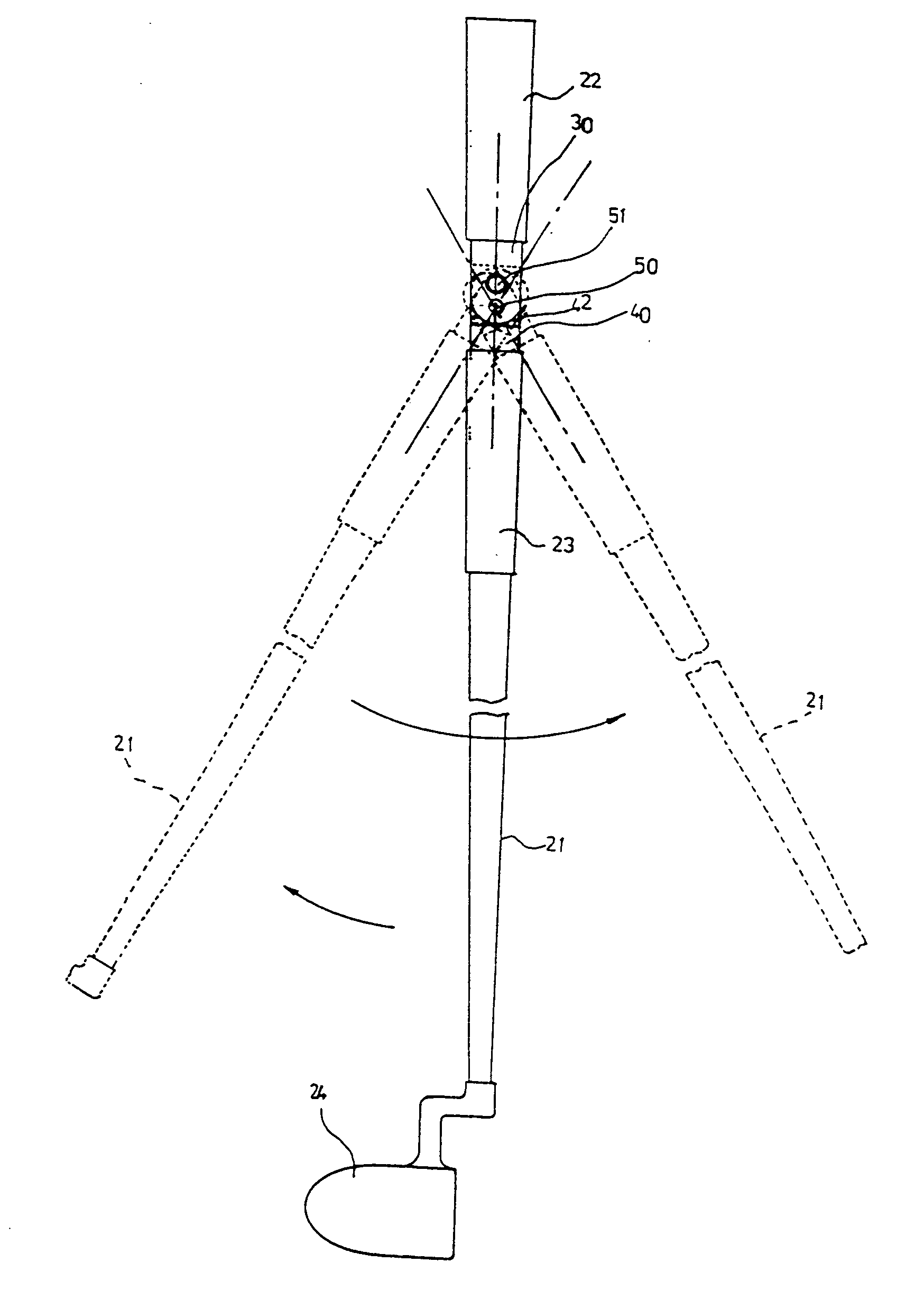
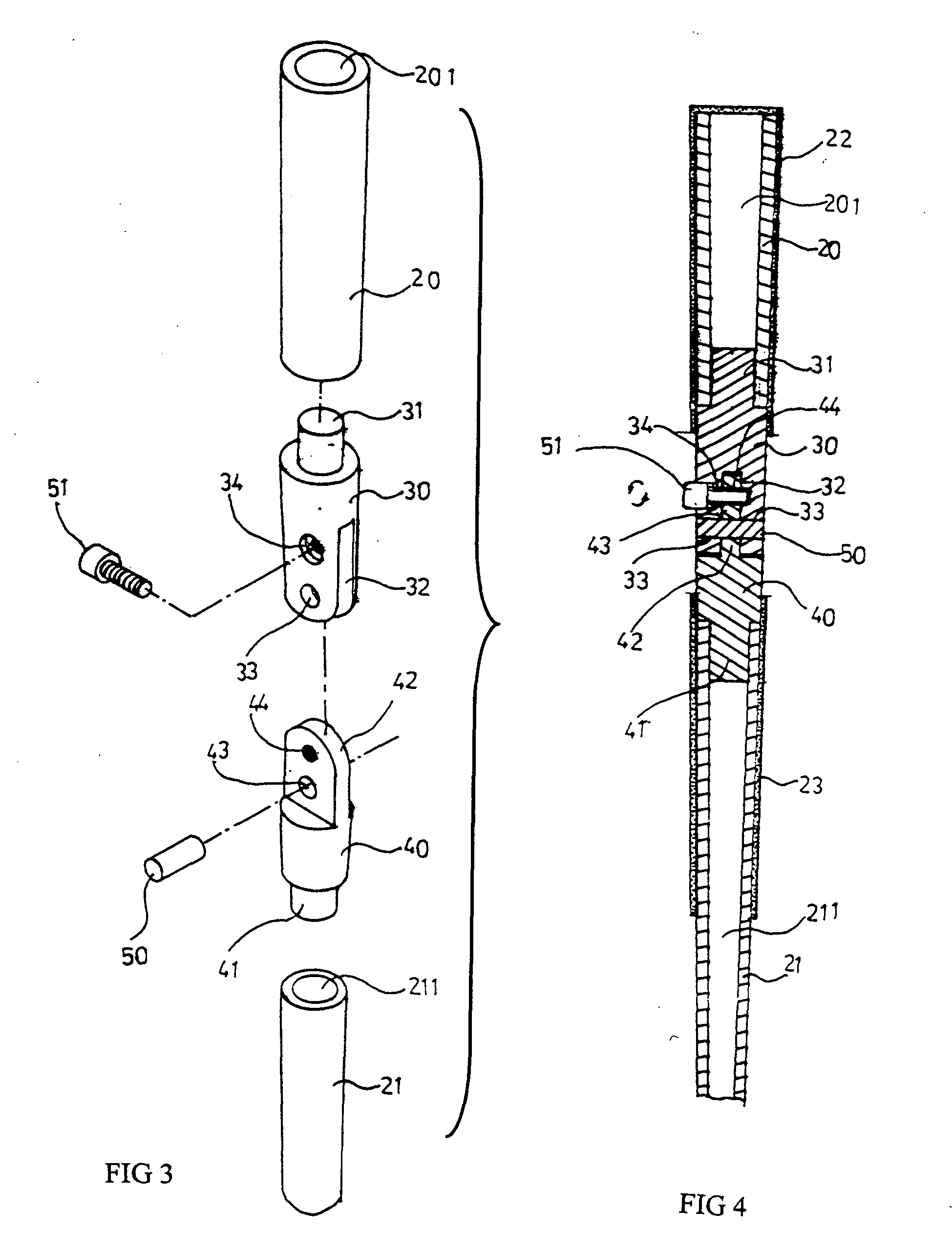
[0013] Referring to FIGS. 3, 4, and 5, the controllable head of the putter mainly consists of two sections of shafts 20, 21 linked by the fork joint.

[0014] The upper shaft 20, same as the conventional part, has a cavity 201 and a grooved handle 22 for player to hold.

[0015] The lower shaft 21, same as the conventional part, has a cavity 211, a grooved handle 23, and a head 24 with a wide face.

[0016] The fork joint comprises a fixed head 30 and a moveable head 40. The fixed head has a joining post 31 on the top which ill enter the cavity 201 of the upper shaft 20. The fixed head 30 has a downward fork 32, a lock hole 33, and a bolt hole 34. The moveable head 40 has a downward post 41 entering into the cavity 211 of the lower shaft 21, a linking tongue 42, a lock hole 43, and a bolt hole 44.

[0017] As shown in FIG. 4, the tongue 42 of the moveable head 40 ...


PUM


Abstract

This invention relates to a controllable head to be used on the golf putter, in which the club shaft is divided into two sections, the upper shaft and the lower shaft, and linked together by a fork joint which provides a relative tendency of stability in sway of the upper shaft against the lower shaft so as to render the ball an accurate rolling course to enter the hole on the green.

Description

FIELD OF THE INVENTION [0001] The invention relates to a controllable head for the golf putter in which the club shaft is divided into two sections, the upper shaft and the lower shaft, and linked together by a fork joint which is easy the player to locate what is the tendency of the propulsion axis the ball will roll on so as to gain more accuracy in the ball rolling course. BACKGROUND OF THE INVENTION [0002] In the golf sports, there are two ways employed to hit the ball, the dynamic striking or the static propulsion, of these two; using putter to propel the ball is most important factor to win or lose the game, so the good skill or the poor skill to employ the putter is a judgment most golf players have to face. [0003] As shown in FIG. 1, it is an appearance of a short putter, the shaft is rather short, and the top end has a gloved handle for the player to hold it with two hands. The head 12 has a wide face. The player holds the gloved handle 12 with two hands and places the putt...

Claims


Application Information

Patent Timeline
IPC IPC(8): A63B53/00A63B53/14A63B53/16A63B59/00A63B69/36
CPCA63B53/007A63B2059/0081A63B53/14A63B60/0081A63B60/00
Inventor HSU, HSIN I.
Owner HSU HSIN I
Why Eureka
Try Eureka