Systems for volumetrically controlling a mixing apparatus

Inactive Publication Date: 2007-07-26
HALLIBURTON ENERGY SERVICES INC
View PDF41 Cites 32 Cited by
  • Summary
  • Abstract
  • Description
  • Claims
  • Application Information

AI Technical Summary

Benefits of technology

[0013]The estimated volume of a material to total materials in a mixing vessel may be determined using a volumetric ratio observer comprising a feedback loop. The volumetric ratio observer advantageously provides for filtered, zero-lag estimations of the actual volumetric ratios within the mixing vessel in a manner that accounts for unwanted disturbances in the system. By way of example, the materials being combined in the mixing vessel may be dry cement and water, and the slurry formed therein may be pumped down a wellbore during a well cementing process. Knowing the relative volumes inside the mixing vessel at any time and thus the relative volumes of the cement and water being pumped downhole may be very useful.
[0014]The volumetric ratio observer may also be employed to estimate the volumetric r

Problems solved by technology

However, this type of control system has a major drawback in that the response of the water and cement control loops are time lagged.
Another drawback of this control system is that often no densitometer is available to measure the output slurry density, or the output slurry density is ill-conditioned to be used as a control variable (i.e., the value of the density of one component being mixed is very close to the value of the density of the other component being mixed in a two-component system).
Using a PI or a PID control system to overcome the physical system nonlinearity results in eigenvalue migration.
Unfortunately, the system is a coupled system in that different portions of the system depend upon each other.
Thus, fine tuning the control system is typically impossible to accomplish due to the differing time- or frequency-domain responses of the diffe

Method used


Image

  • Systems for volumetrically controlling a mixing apparatus
  • Systems for volumetrically controlling a mixing apparatus
  • Systems for volumetrically controlling a mixing apparatus

Examples


examples

[0095]The invention having been generally described, the following examples are given as particular embodiments of the invention and to demonstrate the practice and advantages thereof. It is understood that the examples are given by way of illustration and are not intended to limit the specification or the claims to follow in any manner.

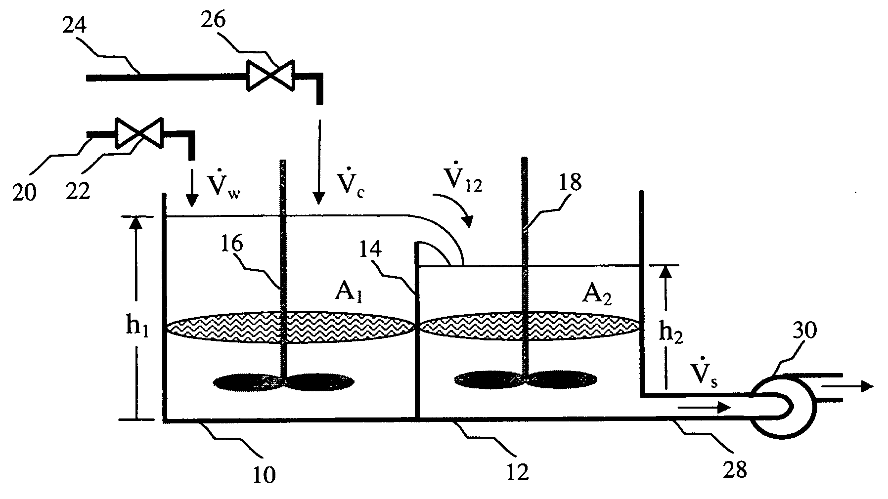
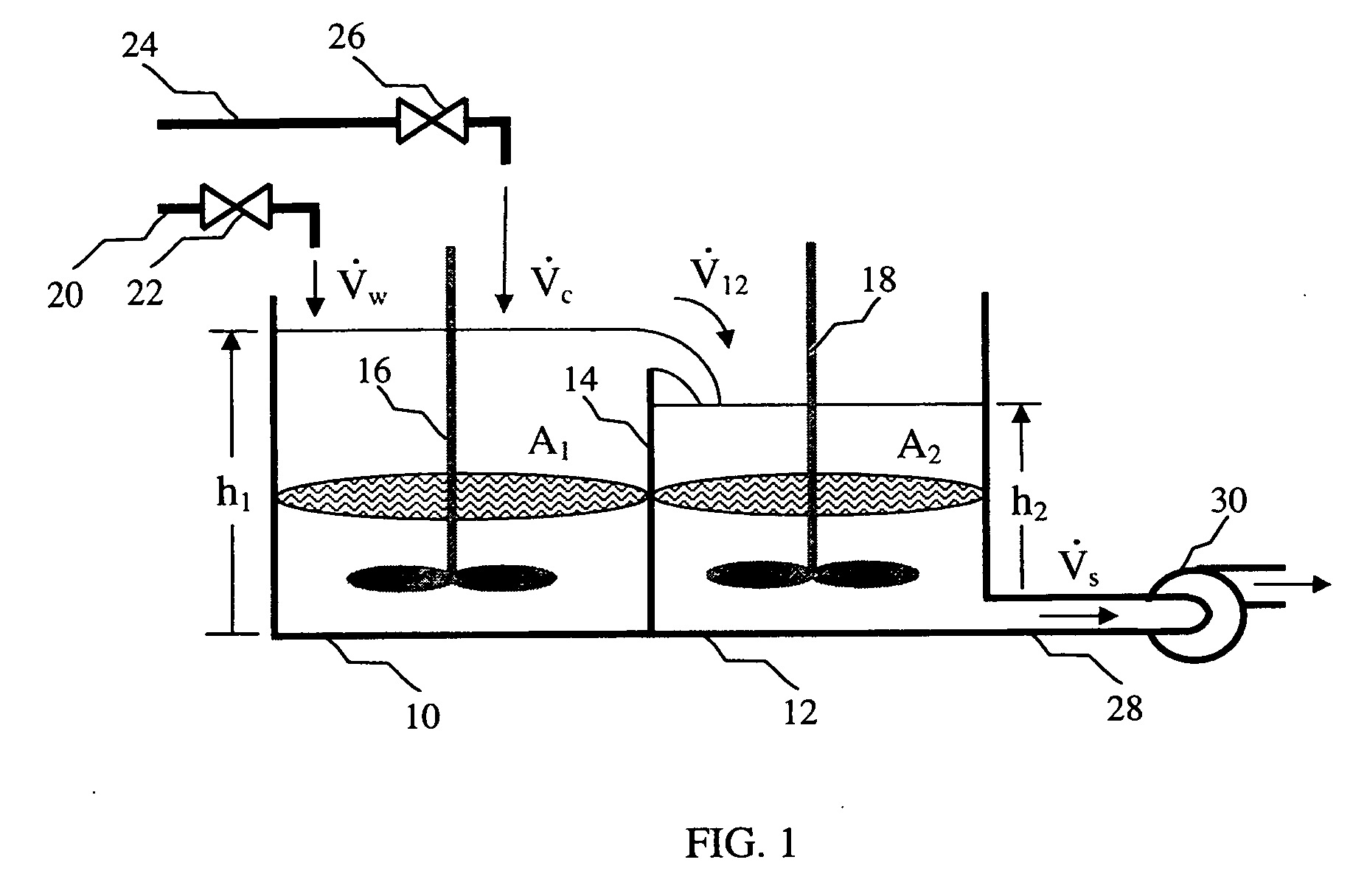
[0096]The mixing apparatus shown in FIG. 1 was assembled and operated using the embodiment of the control scheme shown in FIG. 6. Various parameters of the mixing process were determined and plotted as a function of time in FIG. 10. More specifically, line 550, labeled as the slurry recirculation density, represents the change in the measured slurry density in the first vessel. Line 552, labeled as the Ve_ density represents the change in density as given by the volumetric ratio observer with active disturbance decoupling. Line 554, labeled as the tub level, represents the change in the height of the slurry in the second vessel. Line 556, labeled as ...


PUM


Abstract

Systems are provided for controlling a volumetric ratio of a material to total materials in a mixing vessel. In various embodiments, the systems may comprise: a volumetric ratio observer for estimating the volumetric ratio of the material to the total materials in the mixing vessel and an output flowrate of the material from the mixing vessel; a flow regulator coupled to the volumetric ratio observer for dynamically recomputing a commanded input flowrate of the material based on outputs of the volumetric ratio observer; and a flow modulator coupled to the flow regulator for adjusting an input valve of the material based on the commanded input flowrate of the material. In an embodiment, the mixing vessel comprises a first mixing vessel partially separated from a second mixing vessel. In this case, a height observer may be used to estimate a height of the total materials in the second mixing vessel.

Description

BACKGROUND AND SUMMARY OF THE INVENTION[0001]The present invention generally relates to process control, and more particularly to systems of volumetrically controlling a mixing apparatus.[0002]The following applications filed concurrently herewith are not necessarily related to the present application, but are incorporated by reference herein in their entirety:[0003]“Methods of Determining a Volumetric Ratio of a Material to the Total Materials in a Mixing Vessel” (U.S. application Ser. No. 11 / 323,831, filed simultaneously with the effective filing date of the present application, atty. Docket no. HES-12114U1)[0004]“Systems for Determining a Volumetric Ratio of a Material to the Total Materials in a Mixing Vessel” (U.S. application Ser. No. 11 / 323,323, filed simultaneously with the effective filing date of the present application, atty. Docket no. HES-12114U2); and[0005]“Systems for Volumetrically Controlling a Mixing Apparatus” (U.S. application Ser. No. 11 / 323,322, filed simultane...

Claims


Application Information

Patent Timeline
IPC IPC(8): B01F15/04
CPCB01F13/1013G05D11/133B01F2013/1052B01F15/00207B01F33/81B01F33/834B01F35/213
Inventor DYKSTRA, JASON D.BORGSTADT, JUSTIN A.
Owner HALLIBURTON ENERGY SERVICES INC
Why Eureka
Try Eureka