Structure and method for connecting flexible printed circuit board to inkjet print head

a flexible printed circuit board and inkjet print head technology, applied in the direction of printed circuit non-printed electric components association, soldering apparatus, manufacturing tools, etc., can solve the problems of increasing production costs, requiring higher precision, and poor production yield, so as to achieve high potential for short-circuit occurring by solder bridge between adjacent lands, the effect of increasing accuracy and accurate shape and thickness

Active Publication Date: 2006-06-06
BROTHER KOGYO KK
View PDF8 Cites 32 Cited by
  • Summary
  • Abstract
  • Description
  • Claims
  • Application Information

AI Technical Summary

Benefits of technology

[0006]However, in order to arrange the ejection nozzles with more density, the lands on the flexible printed circuit board must be arranged with higher density. To achieve this, the lands should be formed and spaced with more accuracy. The solder should be formed on the lands with more accurate shape and thickness. Further, the terminals should be positioned accurately over the lands. Therefore, the potential for a short-circuit occurring by solder bridge between adjacent lands is high, resulting in a poor production yield. By staggering the lands for a denser arrangement and forming conducting wires between the lands for connecting to the lands, the distance between the conducting members becomes small, which requires higher precision and increases production costs.

Problems solved by technology

Therefore, the potential for a short-circuit occurring by solder bridge between adjacent lands is high, resulting in a poor production yield.
By staggering the lands for a denser arrangement and forming conducting wires between the lands for connecting to the lands, the distance between the conducting members becomes small, which requires higher precision and increases production costs.

Method used


Image

  • Structure and method for connecting flexible printed circuit board to inkjet print head
  • Structure and method for connecting flexible printed circuit board to inkjet print head
  • Structure and method for connecting flexible printed circuit board to inkjet print head

Examples


first embodiment

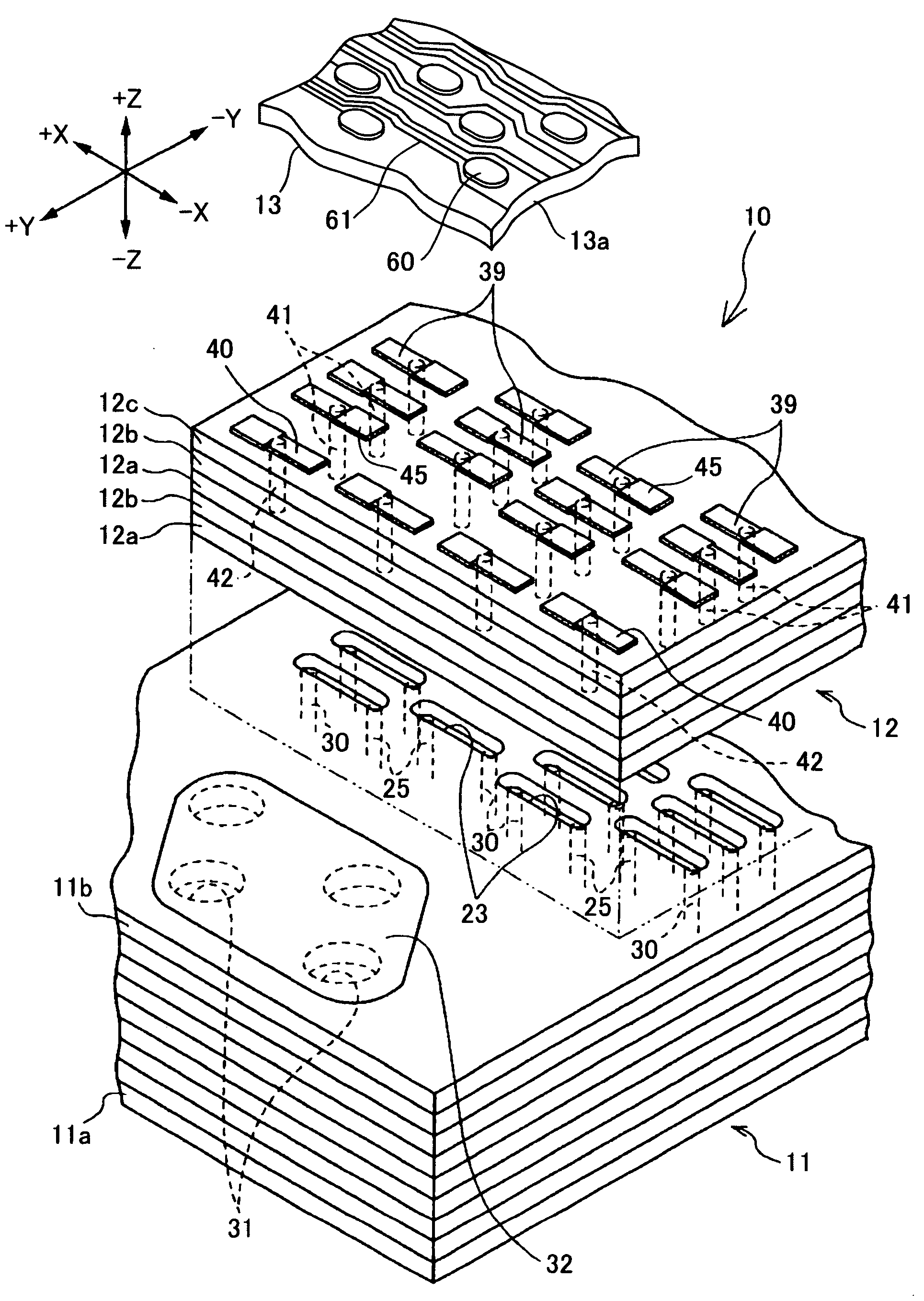
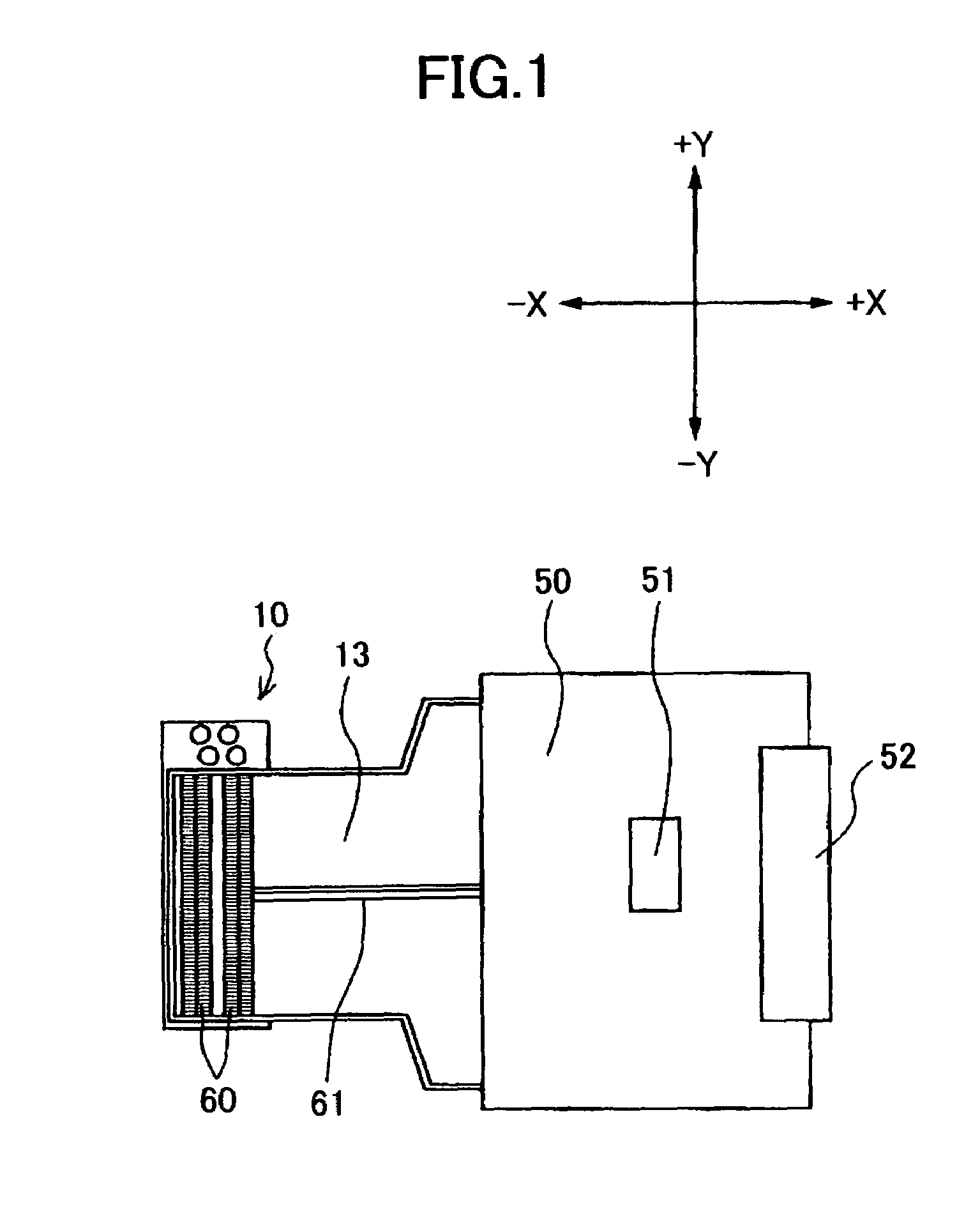
[0036]First, an inkjet head 10, a flexible printed circuit board 13, and a driver circuit board 50 according to a first embodiment of the present invention will be described with reference to FIGS. 1–12.

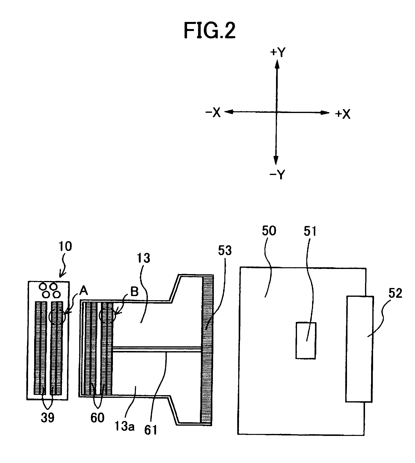
[0037]FIG. 1 is a plan view showing an inkjet head 10, a flexible printed circuit board 13, and a driver circuit board 50 in a connected state. FIG. 2 is a plan view showing the inkjet head 10, the flexible printed circuit board 13, and the driver circuit board 50, which are not yet connected with one another. FIG. 3 is an enlarged perspective view showing a portion of the inkjet head 10 and a portion of the flexible printed circuit board 13. FIG. 4 is an enlarged plan view showing surface electrodes 39 on the inkjet head 10 in an area indicated by the arrow A in FIG. 2. FIG. 5 is an enlarged plan view showing lands 60 on the flexible printed circuit board 13 in an area indicated by the arrow B in FIG. 2. FIG. 6 is an enlarged cross-sectional view taken along a line VI—VI in FIG. 5. ...

second embodiment

[0062]Next, a method and a structure according to a second embodiment of the present invention for connecting the inkjet head 10 to a flexible printed circuit board 113 will be described with reference to FIGS. 13A through 17.

[0063]According to the present embodiment, the inkjet head 10 is connected via the flexible printed circuit board 113 of the present embodiment to a driver circuit board 150 of the present embodiment.

[0064]FIG. 13A is a plan view showing the inkjet head 10, the flexible printed circuit board 113, and the driver circuit board 150 in their connected state. FIG. 13B is a plan view showing the inkjet head 10, the flexible printed circuit board 113, and the driver circuit board 150 in their separate state. FIG. 13C shows a part of the inkjet head 10 and a part of the flexible printed circuit board 113.

[0065]The inkjet head 10 of the present embodiment is the same as that of the first embodiment. The flexible printed circuit board 113 of the present embodiment is dif...


PUM

PropertyMeasurementUnit
conductiveaaaaaaaaaa
flexibleaaaaaaaaaa
electrically insulatingaaaaaaaaaa

Abstract

A plurality of lands and a plurality of conducting wires connected independently to each land are formed on one side surface of an insulating substrate of a flexible printed circuit board. Through-holes are formed through the insulating substrate for exposing the lands to the other side surface. Solder is provided in the through-holes. The solder connects the lands to the head terminals on an inkjet head, which is located facing the other side surface of the insulating substrate. The insulating substrate separates the solder from areas between the conducting wires and from areas between the lands, thereby preventing short circuits from occurring when manufacturing the connecting structure with a low tolerance grade.

Description

BACKGROUND OF THE INVENTION[0001]1. Field of the Invention[0002]The present invention relates to a structure and method for connecting a flexible printed circuit board to an inkjet print head in an inkjet recording device.[0003]2. Description of Related Art[0004]Conventional inkjet recording devices perform color printing using four ink cartridges for colors of cyan, magenta, yellow, and black, for example. A holder for accommodating and holding these ink cartridges is provided with: four inkjet heads for ejecting each color of ink, and circuit boards for driving these inkjet heads. These inkjet heads and circuit boards are connected via flexible circuit boards to form a print head unit. Ink is supplied from the ink cartridges to the inkjet heads, and images are recorded by ejecting ink through ejection nozzles.[0005]As the density of these ejection nozzles has increased along with improvements in recording quality of recent years, the terminals of these inkjet heads and the lands o...

Claims


Application Information

Patent Timeline
Patent Type & Authority Patents(United States)
IPC IPC(8): B41J2/05B23K1/00B41J2/16B41J2/045B41J2/055B41J29/00H05K1/18H05K3/34H05K3/36
CPCB23K1/0016H05K3/363B23K2201/42H05K3/3452H05K2203/043H05K2201/09472H05K2201/09709H05K2201/099H05K2201/0394B23K2101/42
Inventor IMAI, KOJIHIWADA, SHUHEI
Owner BROTHER KOGYO KK
Why Eureka
Try Eureka