Massaging apparatus

a technology of massage apparatus and rollers, which is applied in the field of massage apparatus, can solve the problems of increasing trouble, reducing the service life of the massage apparatus, so as to prevent the base body from slipping, the effect of convenient and fast assembly

Inactive Publication Date: 2005-03-03
LEE CHIN TSUN
View PDF21 Cites 42 Cited by
  • Summary
  • Abstract
  • Description
  • Claims
  • Application Information

AI Technical Summary

Benefits of technology

[0005] The objective of the invention is to offer a massaging apparatus able to be assembled conveniently and quickly and to prevent its base body from slipping.

Problems solved by technology

However, the conventional massaging apparatus 1 is mostly made of wood or plastic; therefore when a user's feet soles moves to and fro on the rollers 13, the massaging apparatus 1 is likely to slip, rendering the rollers 13 unable to roll smoothly.
Besides, to assemble the conventional massaging apparatus 1, the rollers 13 have to be respectively fitted on the shafts 12 one by one, and then the shafts 12 are assembled between the two bases 10, increasing trouble and wasting time in assembling.

Method used


Image

  • Massaging apparatus
  • Massaging apparatus
  • Massaging apparatus

Examples


second embodiment

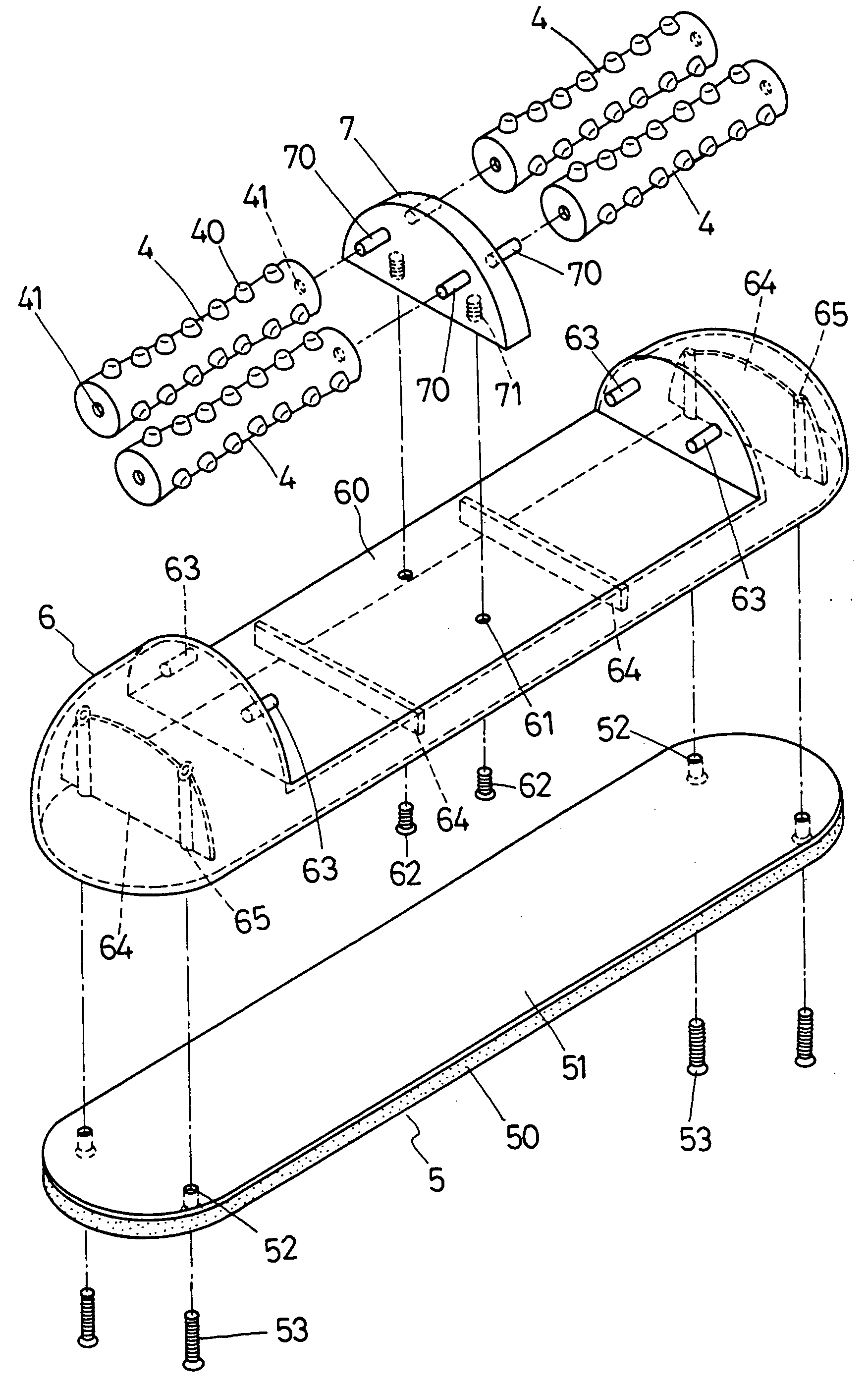
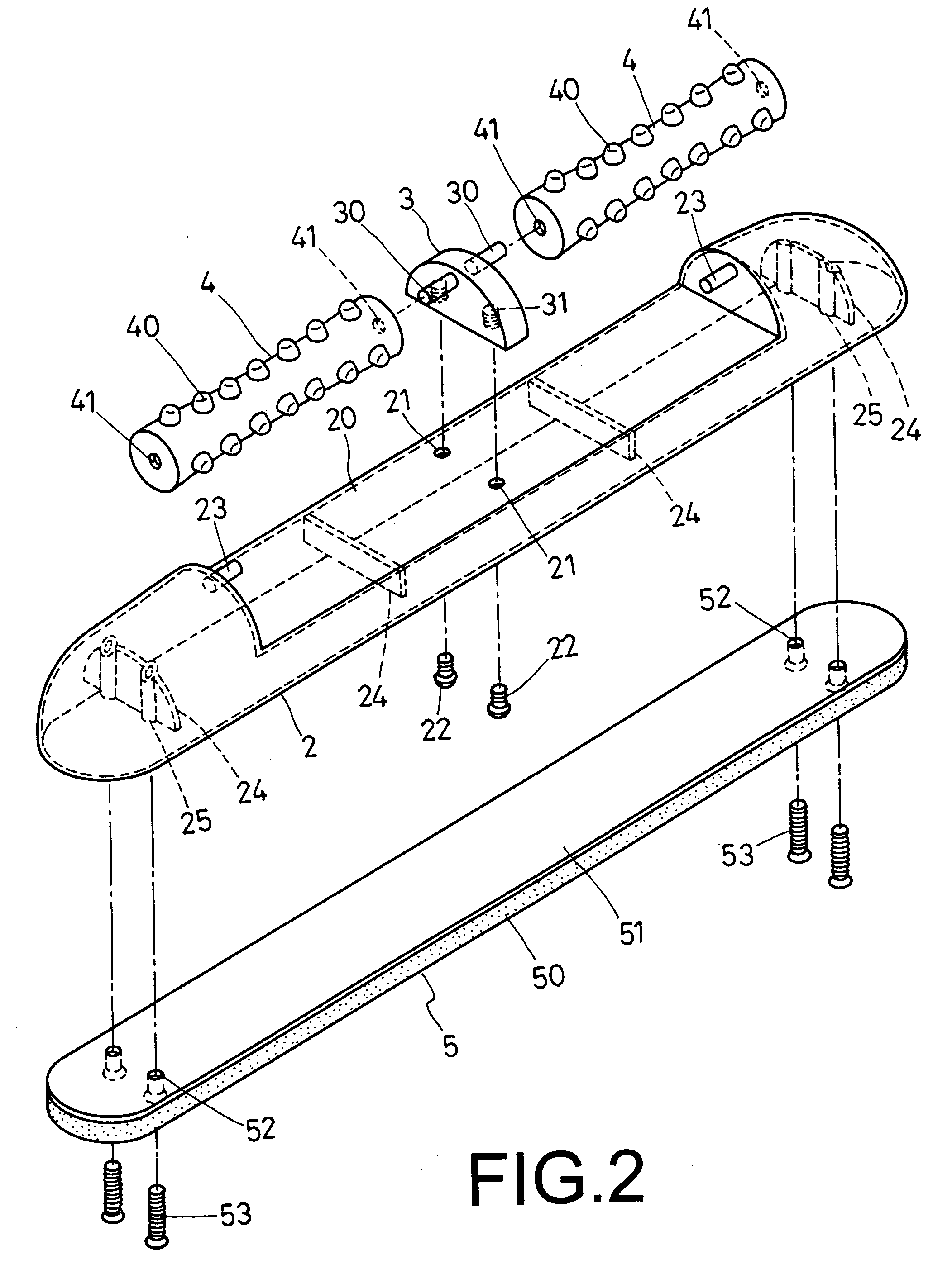
[0023] A second preferred embodiment of a massaging apparatus in the present invention, as shown in FIG. 5, is to have the opposite walls of the recess 20 of the base body 2 respectively bored with a shaft hole 26 instead of the projecting stud 23 in the first preferred embodiment, and the positioning base 3 has its opposite sides respectively bored with a through shaft hole 32 instead of the original projecting stud 30, and further the two massaging bodies 4 have the opposite ends respectively fixed with a transverse projecting stud 42 in place of the original shaft hole 41. In assembling, the projecting studs 42 on the opposite ends of each massaging body 4 are respectively inserted in the shaft hole 26 of the base body 2 and the shaft hole 32 of the positioning base 3. Next, the positioning base 3 is fixed in the recess 20 of the base body 2 by two bolts 22 and the slip-preventing pad 5 is fixedly assembled under the base body 2 by bolts 53 to finish assembly of the massaging app...

fourth embodiment

[0034] In assembling the fourth embodiment, the massaging body 4 has its projecting studs 42 respectively inserted in the shaft hole 81 of the base body 8 and the shaft hole 32′ of the positioning base 3′. Next, the positioning base 3′ is positioned in the recess 80 of the base body 8, letting its threaded holes 31′ aligned to the insert holes 84 of the base body 8 and the insert holes 92 of the slip-preventing pad 9. Then, two bolts 93 are respectively inserted upward through the insert holes 92 of the slip-preventing pad 9 and the insert holes 84 of the base body 8 and then screwed with the threaded holes 31′ of the positioning base 3′, and another two bolts 93 are respectively inserted through the insert holes 92 of the slip-preventing pad 9 and screwed with the fixing posts 83 of the base body 8 to fix the massaging body 4, the positioning base 3′ and the slip-preventing pad 9 on the base body 8.

[0035] As can be noted from the above description, this invention has the following ...


PUM


Abstract

A massaging apparatus includes a base body formed with a recess having insert holes. The recess has the opposite vertical walls respectively provided with a projecting stud. A positioning base assembled in the recess has two projecting studs respectively secured on the opposite sides and threaded holes in the bottom. Massaging bodies are fitted between the recess and the positioning base, having opposite ends respectively bored with a shaft hole. A slip-preventing pad assembled under the base body consists of a soft pad body and a hard board provided on the pad body. In assembling, each massaging body has its shaft holes respectively inserted with the projecting stud of the base body and the positioning base which is then fixed in the cut groove of the base body by bolts.

Description

BACKGROUND OF THE INVENTION [0001] 1. Field of the Invention [0002] This invention relates to a massaging apparatus, particularly to one having a base body formed with a lengthwise recess having two insert holes in the intermediate portion for two bolts to be inserted therethrough. The recess has its opposite walls respectively provided with a transverse projecting stud. A positioning base fixed in the recess of the base body has two transverse projecting studs respectively secured on the opposite sides and two threaded holes bored in the bottom side. Two massaging bodies are respectively assembled between the recess of the base body and the positioning base, and each massaging body has its opposite ends respectively bored with a shaft hole. A slip-preventing pad assembled under the base body consists of a soft pad body and a hard board provided on the topside. In assembling, each massaging body has its shaft holes respectively inserted with the projecting studs of the base body and...

Claims


Application Information

Patent Timeline
Patent Type & Authority Applications(United States)
IPC IPC(8): A61H15/00
CPCA61H2015/0014A61H15/00
Inventor LEE, CHIN-TSUN
Owner LEE CHIN TSUN
Why Eureka
Try Eureka