Antenna structure assembly

a technology of antenna structure and assembly, which is applied in the direction of antennas, antenna feed intermediates, antenna details, etc., can solve the problems of complex manufacturing and assembly of antenna structure, and achieve the effects of reducing manufacturing costs, simplifying antenna structure, and convenient assembly

Inactive Publication Date: 2008-11-04
SMARTANT TELECOMM
View PDF6 Cites 10 Cited by
  • Summary
  • Abstract
  • Description
  • Claims
  • Application Information

AI Technical Summary

Benefits of technology

[0009]Accordingly, the present invention is mainly directed to provide a simplified antenna structure, which has a reduced manufacturing cost and meanwhile can be assembled quickly and conveniently.
[0012]Based on the above description, the hollow bolt of the antenna of the present invention is used to fix the antenna onto a wall or ceiling and can also be used as a cable connector, such that the antenna has a simplified structure and a low manufacturing cost and the assembly of this antenna is more convenient and quick.

Problems solved by technology

However, it is troublesome to install the antenna structure in two procedures, and besides that, it is also complex to manufacture and assemble the antenna structure as the antenna has a lot of parts.

Method used


Image

  • Antenna structure assembly
  • Antenna structure assembly
  • Antenna structure assembly

Examples


Embodiment Construction

[0022]In order to further understand the technical contents and constitutive components of the present invention, the present invention will be illustrated below with reference to the drawings. However, the accompanied drawings are only for reference and illustration and are not intended to limit the present invention.

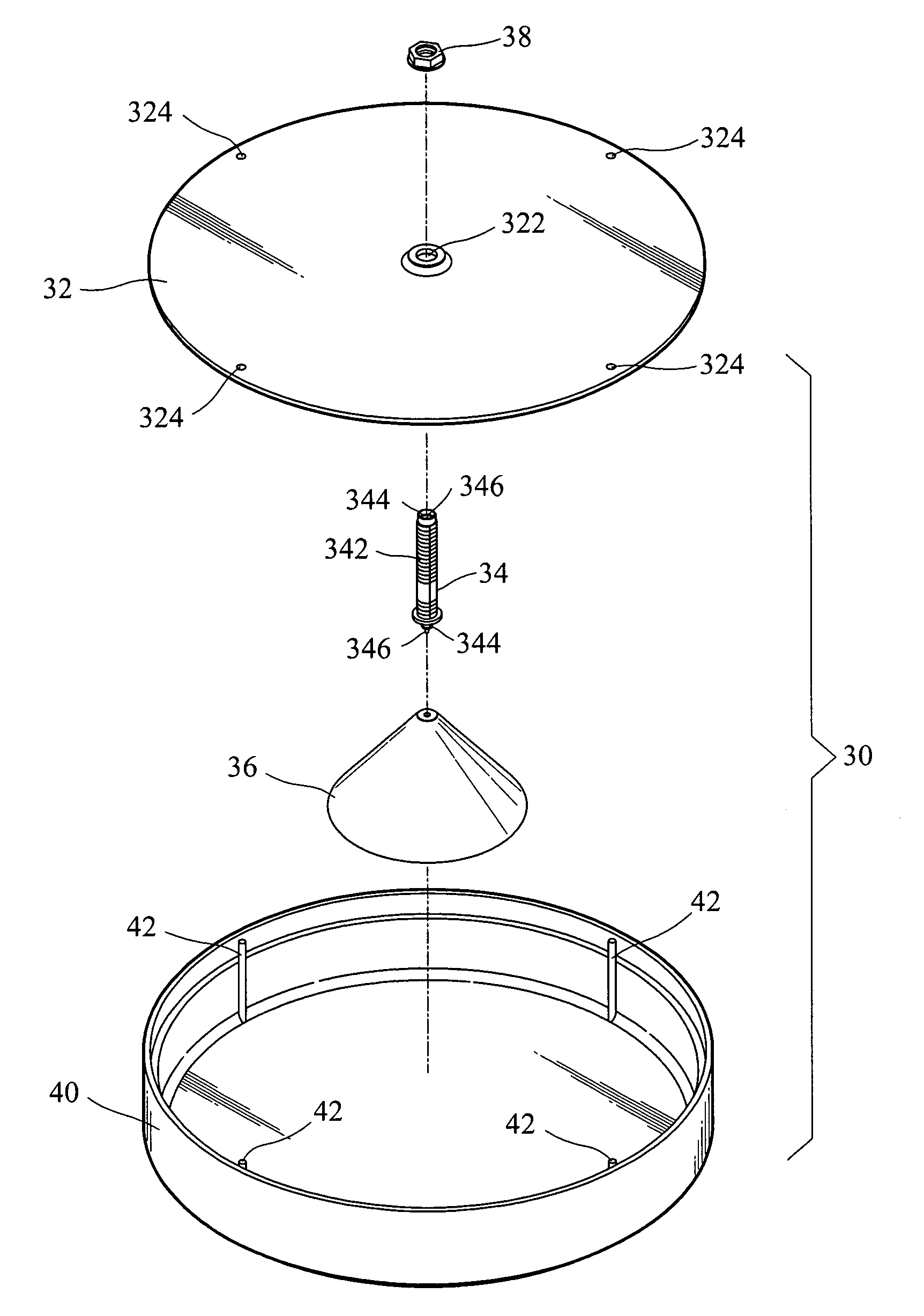
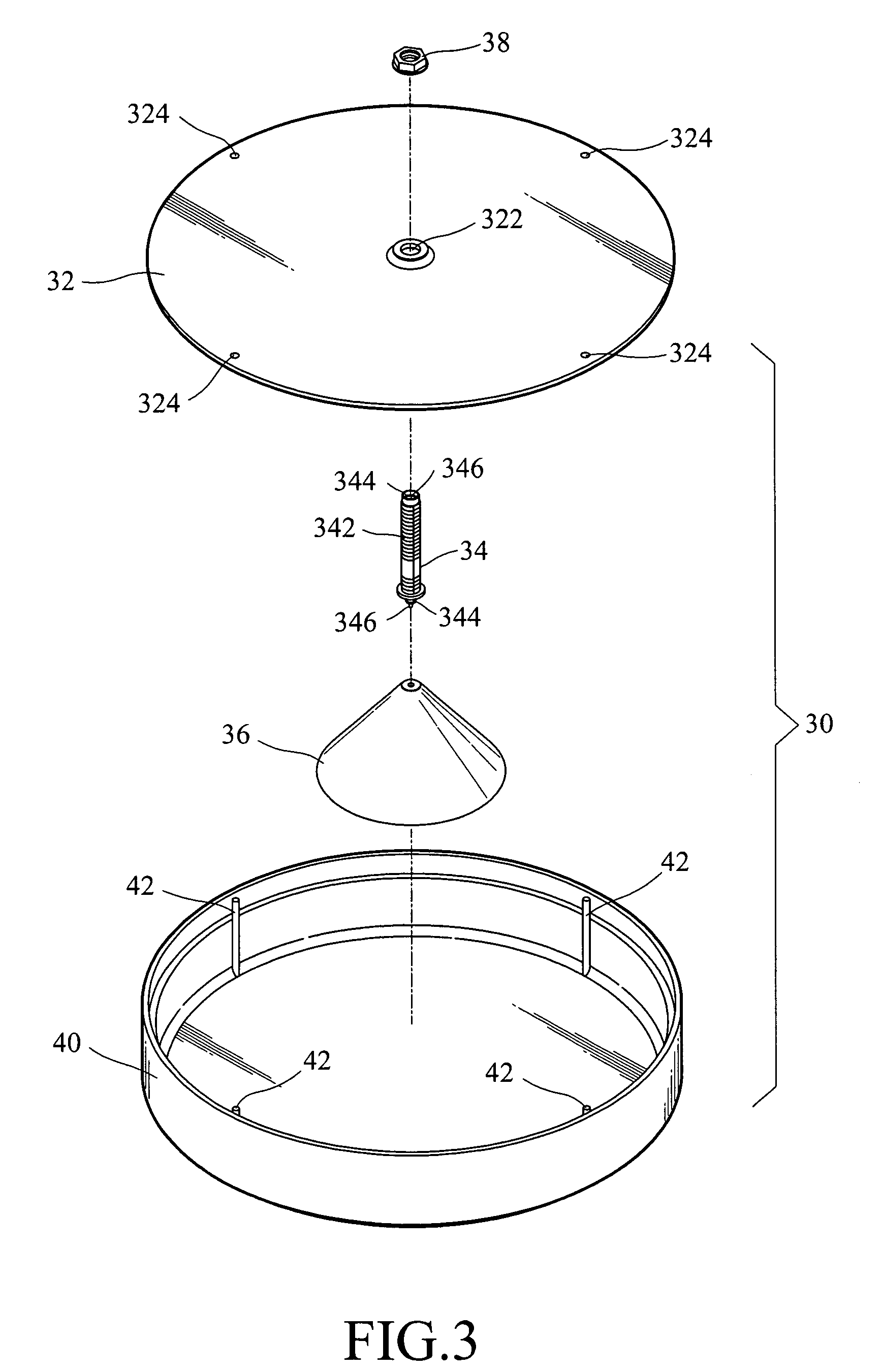
[0023]Referring to FIGS. 3 and 4, an antenna structure of an embodiment of the present invention is provided. As shown in the figures, the antenna 30 includes a ground plate 32, a hollow bolt 34, and a conductive conical dome 36.

[0024]The ground plate 32 is made of metal and has a through hole 322 formed on the central portion thereof. The ground plate 32 has a plurality of tenon holes 324 formed thereon, wherein the tenon holes 324 are formed near the outer edge of the ground plate 32 and spaced to one another with equal intervals. The hollow bolt 34 is a hollow pipe with a thread 342 formed on its outer peripheral surface, an insulator 344 is inserted into the hollow...


PUM


Abstract

An antenna structure including a ground plate, a hollow bolt, and a conductive conical dome is provided. The hollow bolt passes through the ground plate, and a signal wire is laid in the hollow bolt. An insulator is disposed between the signal wire and the hollow bolt for providing electrical isolation therebetween. The conductive conical dome is connected with one end of the signal wire. The hollow bolt and a nut are provided to fix the antenna on a wall or a ceiling. Since the signal wire is laid in the hollow bolt, the signal wire can be connected to a signal source only by connecting a signal cable to the hollow bolt.

Description

CROSS-REFERENCE TO RELATED APPLICATIONS[0001]This non-provisional application claims priority under 35 U.S.C. §119(a) on Patent Application No(s). 094220085 filed in Taiwan, R.O.C. on Nov. 18, 2005, the entire contents of which are hereby incorporated by reference.BACKGROUND OF THE INVENTION[0002]1. Field of Invention[0003]The present invention relates to an antenna structure, and more particularly to an antenna structure that can be attached onto a ceiling, a wall, or a partition wall.[0004]2. Related Art[0005]Antennas are provided for emitting and receiving electric waves, and based on operating bands, antennas can be classified into ultra-long wave, long wave, medium wave, short wave, ultra-short wave, and microwave antennas from low frequency to high frequency. The antennas have been widely applied in military and civilian communication. The sizes and lengths of antennas are quite different according to different operating bandwidths and wave lengths, and antennas can also be cl...

Claims


Application Information

Patent Timeline
Patent Type & Authority Patents(United States)
IPC IPC(8): H01Q1/42
CPCH01Q9/28H01Q9/40
Inventor SONG, JIA-JIUYANG, SHENG-HSIUNGJENG, JR-RENHSUEH, MU-KUN
Owner SMARTANT TELECOMM
Why Eureka
Try Eureka