Cross flow fan

a technology of cross-flow fan and assembly housing, which is applied in the direction of machines/engines, mechanical equipment, liquid fuel engines, etc., can solve the problems of poor structural strength of assembled housing, inability to achieve the required streamline design, and complex manufacturing, etc., to enhance the overall strength and the operation of the fan, and quick and convenient assembly

Inactive Publication Date: 2011-08-30
KO CHEN HUI
View PDF2 Cites 7 Cited by
  • Summary
  • Abstract
  • Description
  • Claims
  • Application Information

AI Technical Summary

Benefits of technology

[0009]It is a primary object of the invention to provide an improved cross flow fan assembly, wherein its housing and cross flow fan are made of a plastic material and skillfully assembled into a plastic cross flow fan module. The invention not only provides a quick and convenient assembling, but also enhances the overall strength and the operation of the fan.
[0010]Another objective of the present invention is to provide an improved cross flow fan assembly, and the cross flow fan comes with a vibration resisting design for preventing vibrations and reducing noises, and thus the cross flow fan is applicable for fitness equipments.

Problems solved by technology

With the weight limitation, the metal plates cannot be too thick, and thus the structural strength of the assembled housing 11 is poor.
However, most of these cross flow fans 10 are made of metals, and most of the connections are achieved by stamping, riveting and welding, and thus the manufacture is more complicated, and the required streamline design cannot be achieved easily.
If the cross flow fan 13 is driven by the motor 12 to rotate transversally in the x-x direction, and the length L of the cross flow fan 11 is slender, the circularity of the riveted metal vanes 131 will be affected, and the operation of the fan will become unsmooth, and thus such fan is not suitable to be installed in the panel meter of the fitness equipment.
Although the problems created by the metal material and its rivet connection do not affect the usage of industrial products, yet the prior art is not suitable to be used in a panel meter installed with precision electronic components.

Method used


Image

  • Cross flow fan
  • Cross flow fan
  • Cross flow fan

Examples


Embodiment Construction

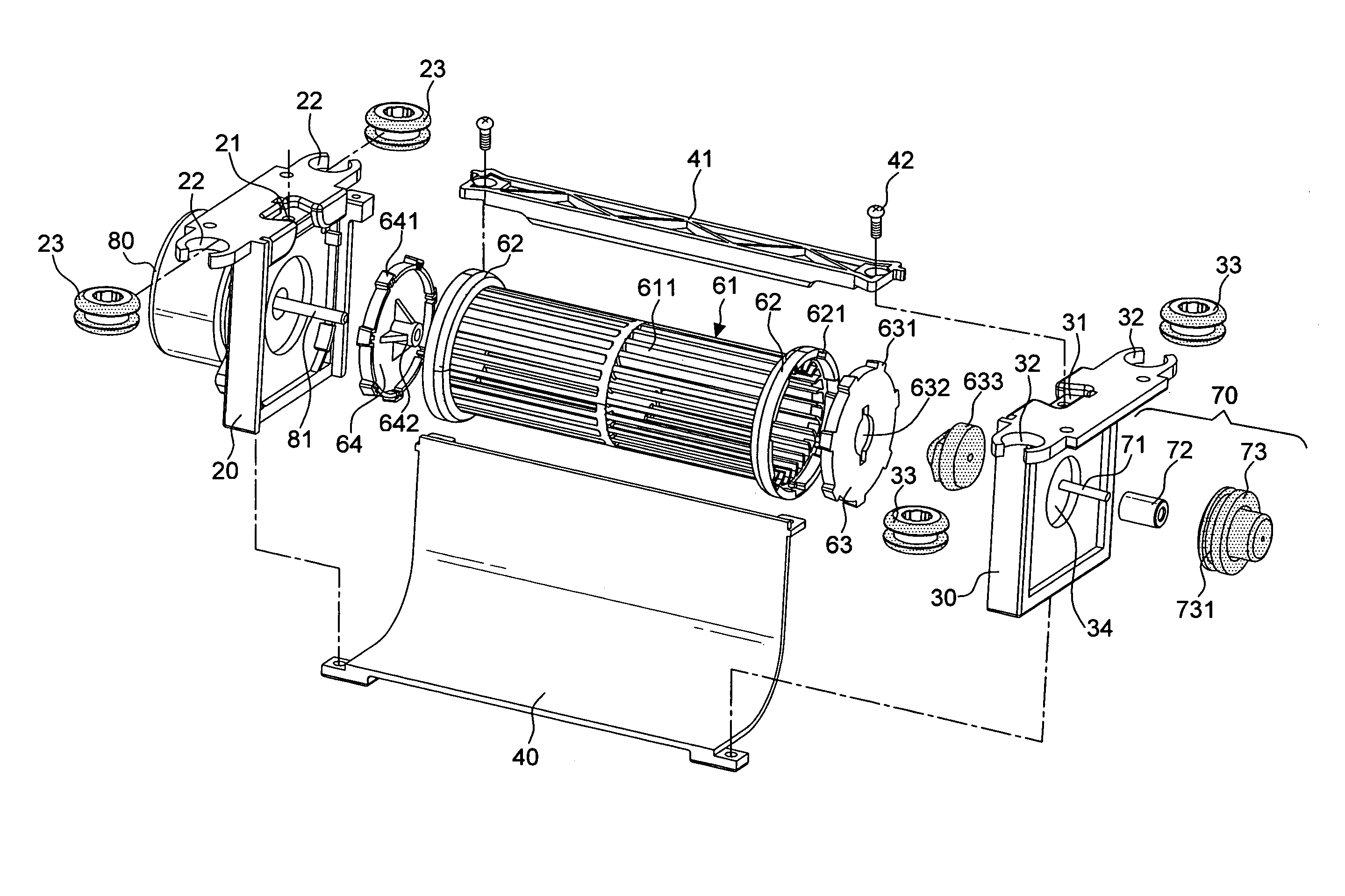
[0028]Referring to FIGS. 4 to 7, a preferred embodiment of the present invention comprises: a housing 50, made of a plastic material, and having a left panel 20, a right panel 30, and an L-shape baffle 40; a cross flow fan 60, also made of a plastic material, and installed between the left and right panels 20, 30; and a motor 80, installed on an external side of the left panel 20, and its axle 81 is extended into an internal side for driving the cross flow fan 60.

[0029]The assembly of the housing 50 and the cross flow fan 60 in accordance with the present invention further comprises a fan body 61, as shown in FIG. 5, being integrally formed by plastic injection molding into a cylindrical body that includes a plurality of long vanes 611 disposed transversally along the x-x direction and arranged in a circular shape, and symmetrical circular flanges 62 are formed on both lateral sides of the fan body 61. Since the entire fan body 61 is integrally formed by plastic injection molding, t...


PUM


Abstract

An improved cross flow fan assembly applicable but not limited to a panel meter of fitness equipments includes: a housing and a cross flow fan made of plastic; a fan body, having symmetric circular flanges integrally formed on both lateral ends by plastic injection molding; two side covers, embedded into two circular flanges; and a shock absorption positioning member, installed at an external side of the right panel, and including: an axle center with a front section embedded into a bushing of the right cover and a rear section sheathed into a bearing, and a rubber pad, embedded into a circular hole of the right panel by its circular groove at the periphery for wrapping the bearing, so as to constitute a plastic cross flow fan module, and achieving a fast and convenient assembling and a vibration resisting effect, and the fan comes with a smooth operation to reduce noises.

Description

BACKGROUND OF THE INVENTION[0001]1. Field of the Invention[0002]The present invention relates to a cross flow fan, and more particularly to a cross flow fan applicable but not limited to a panel meter of a fitness equipment, and the cross flow fan and its housing are made of a plastic material.[0003]2. Description of the Related Art[0004]As exercisers often sweat a lot when working on fitness equipments, it is delightful to have steady cool air blowing directly at the exercisers while they are doing exercises. Referring to FIG. 1 for a conventional treadmill machine M, the treadmill machine M includes an axial flow fan installed separately on both sides of a panel meter, and the airflow direction of this type of fan is parallel to the axle. In other words, air is flowing upward instead of blowing directly at an exerciser on the treadmill machine, and such arrangement obviously requires improvements.[0005]Referring to FIGS. 2 and 3 for schematic views of a conventional cross flow fan...

Claims


Application Information

Patent Timeline
Patent Type & Authority Patents(United States)
IPC IPC(8): F04D5/00F04D29/66
CPCF04D17/04F04D29/668
Inventor KO, CHEN-HUI
Owner KO CHEN HUI
Why Eureka
Try Eureka