Cross flow fan structure

Active Publication Date: 2010-06-24
KO CHEN HUI
View PDF4 Cites 9 Cited by
  • Summary
  • Abstract
  • Description
  • Claims
  • Application Information

AI Technical Summary

Benefits of technology

[0009]An object of the invention is to provide a cross flow fan structure wherein its housing and cross flow fan are made of a plastic material and skillfully assembled

Problems solved by technology

With the weight limitation, the metal plates cannot be too thick, and thus the structural strength of the assembled housing 11 is poor.
However, most of these cross flow fans 10 are made of metals, and most of the connections are achieved by stamping, riveting and welding, and thus the manufacture is more complicated, and the required streamline design cannot be achieved easily.
If the cross flow fan 13 is driven by the motor 12 to rotate transversally in the x-x direction, and the le

Method used


Image

  • Cross flow fan structure
  • Cross flow fan structure
  • Cross flow fan structure

Examples


Embodiment Construction

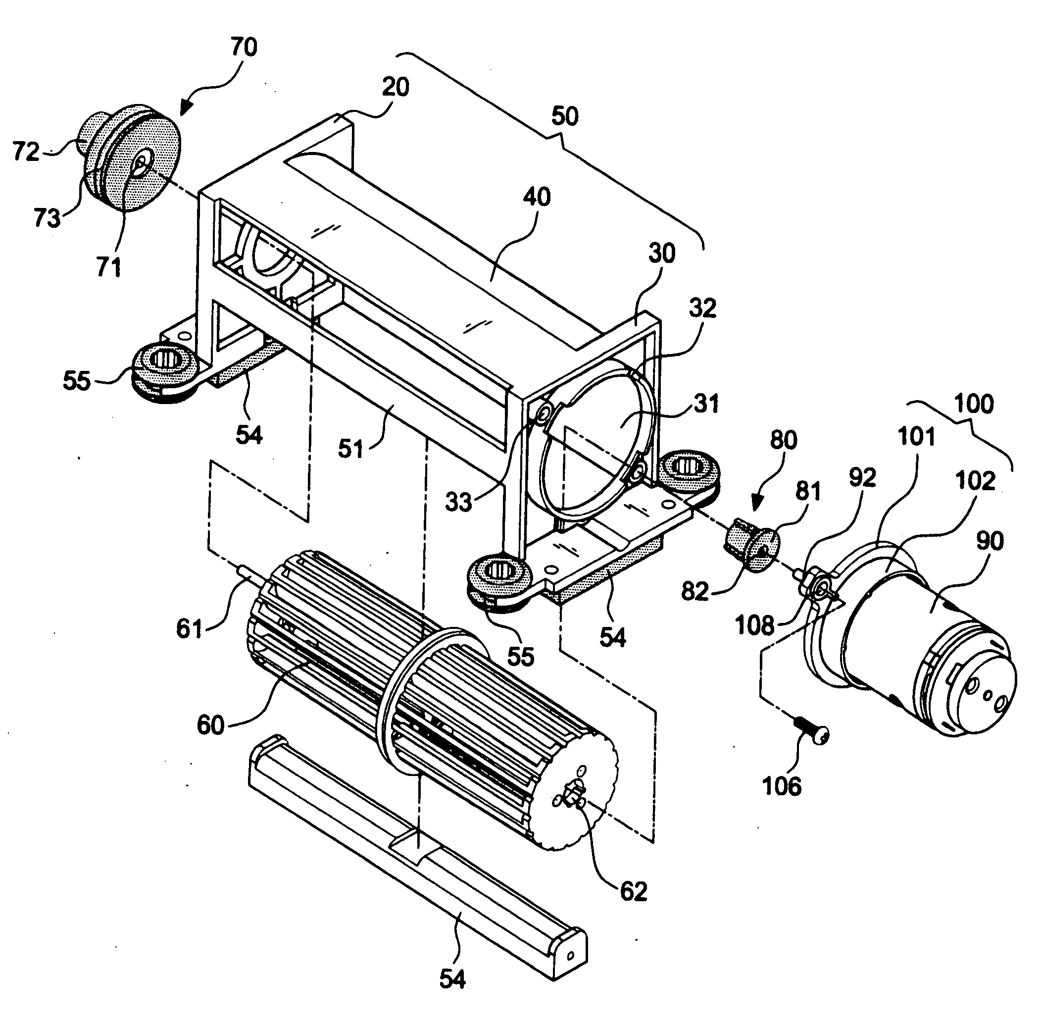
[0031]First of all, referring to FIGS. 4A, 4B through 8, a preferred embodiment in accordance with of the invention includes a housing 50, a first damping / positioning body 70, a cross flow fan 60, a second damping / positioning body 80, a motor 90, and a mounting base 100.

[0032]The housing 50 is integrally formed by plastic material in an injection molding process. The housing 50 includes a left side plate 20, a right side plate 30, and an L-shaped air deflector 40 disposed between both side plates. According to a preferred embodiment, the L-shaped air deflector 40 is formed in an arched shape for achieving a smooth flow guide. Moreover, a cross rib 51 is integrally formed at the front side of the L-shaped air deflector 40 between the left and right side plates 20, 30 for strengthening the structure of the housing 50. In addition, the left side plate 20 includes a first mounting hole 21 while the right side plate 30 has a second mounting hole 31 with a greater diameter. A flange 32 is...


PUM


Abstract

A cross flow fan structure comprising: a) a housing integrally formed by plastic material in an injection molding process; b) a cross flow fan integrally formed by plastic material in an injection molding process, the right side of the cross flow fan having a mounting hole in axial direction and a damping/positioning body; c) a motor with an end portion attached to a mounting base whereupon the motor is attached to the housing by use of the mounting base in such a way that the driving shaft of the motor is extended into the mounting hole of the damping/positioning body in a tightly clamping state for driving the cross flow fan in rotational operation. In this way, a cross flow fan module made by material is created. Moreover, a convenient assemble and a vibration resisting effect are achieved for a smooth operation with low noise by use of a skillful combination of the material and by a special structure.

Description

BACKGROUND OF THE INVENTION[0001]1. Field of the Invention[0002]The invention relates to a cross flow fan, and more particularly to a cross flow fan applicable but not limited to a panel meter of a fitness equipment, and the cross flow fan and its housing are made of a plastic material.[0003]2. Description of the Related Art[0004]As exercisers often sweat a lot when working on fitness equipments, it is delightful to have steady cool air blowing directly at the exercisers while they are doing exercises. Referring to FIG. 1 for a conventional treadmill machine M, the treadmill machine M includes an axial flow fan installed separately on both sides of a panel meter, and the airflow direction of this type of fan is parallel to the axle. In other words, air is flowing upward instead of blowing directly at an exerciser on the treadmill machine, and such arrangement obviously requires improvements.[0005]Referring to FIGS. 2 and 3 for schematic views of a conventional cross flow fan assembl...

Claims


Application Information

Patent Timeline
IPC IPC(8): F04D5/00
CPCF04D29/626F04D17/04F16D3/76
Inventor KO, CHEN-HUI
Owner KO CHEN HUI
Why Eureka
Try Eureka