Side-hung door or window single latch lock

a single latch, side-hung technology, applied in the direction of wing knobs, keyhole guards, mechanical equipment, etc., can solve the problems of troublesome and time-consuming mounting procedure, lock structure complexity, and damage to the strength of the door body

Active Publication Date: 2011-08-04
CMECH (GUANGZHOU) INDUSTRIAL LTD
View PDF14 Cites 7 Cited by
  • Summary
  • Abstract
  • Description
  • Claims
  • Application Information

AI Technical Summary

Problems solved by technology

Conventional insertion-core lock bodies and ball-shaped lock bodies are structurally simpler and on the lower side in cost and price, but they have the following drawbacks: when they are mounted, the door body structure must be destroyed: a groove must be opened in one of the longitudinal sides of the door body to receive the lock body itself and allow for extension and retraction of the latch; the mounting procedure is troublesome

Method used


Image

  • Side-hung door or window single latch lock
  • Side-hung door or window single latch lock
  • Side-hung door or window single latch lock

Examples


embodiment 1

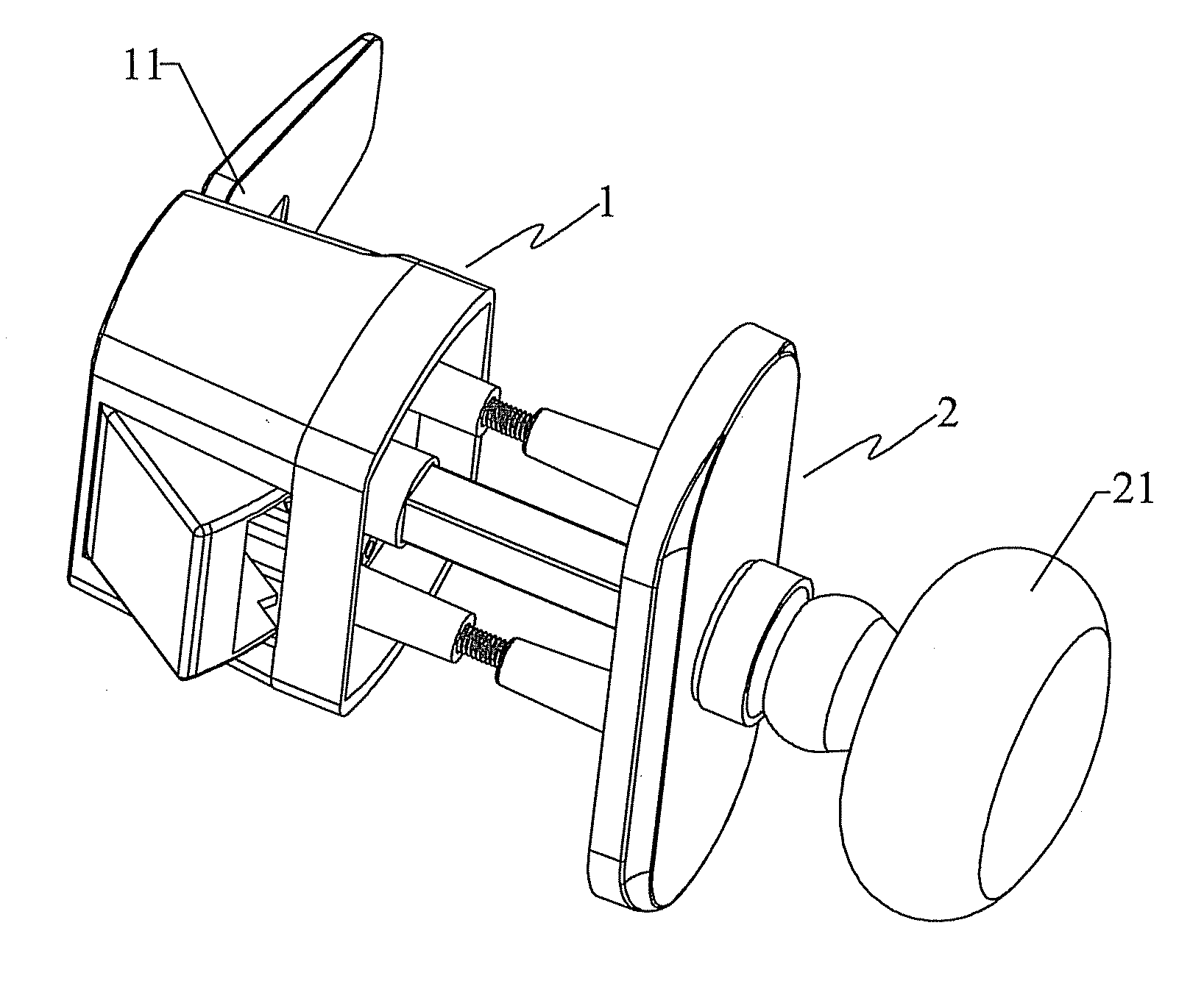
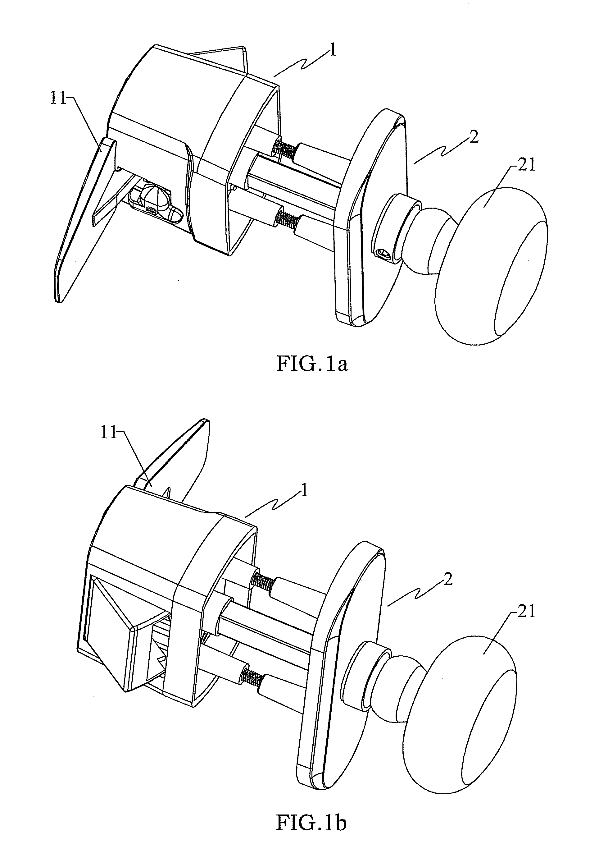
[0019]As shown in FIGS. 1a and 1b, the side-hung door and window single latch lock according to the present utility model comprises a first lock body 1 and a second lock body 2 disposed on an inner side and an outer side of a door or window and sandwiching the door or window in between, wherein the first lock body 1 is disposed on the inner side of the door or window and comprises a first handle 11, and wherein the second lock body 2 is disposed on the outer side of the door or window and comprises a second handle 21.

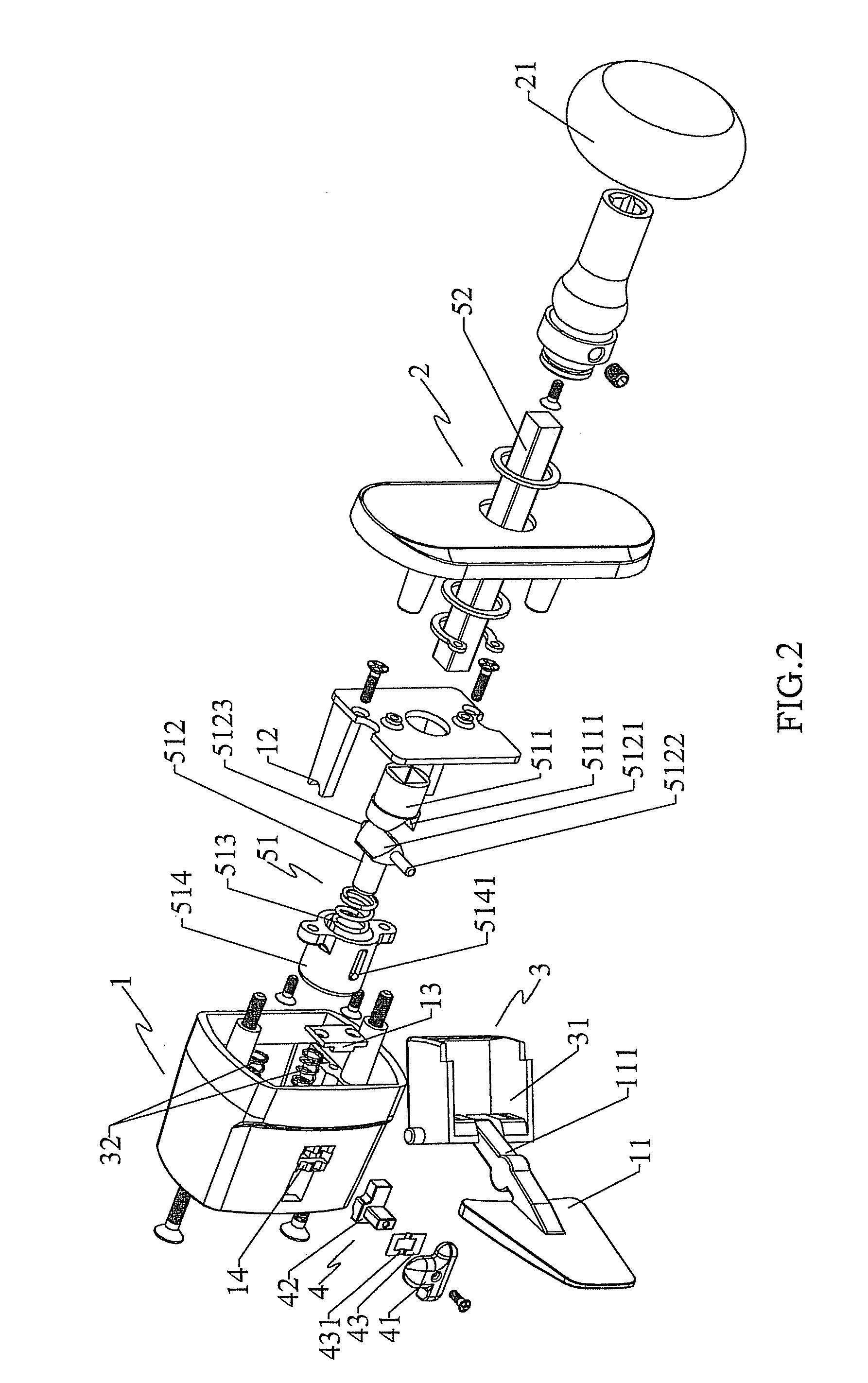
[0020]As shown in FIGS. 2-4, the first lock body 1 further comprises a latch assembly 3 linked to the first handle 11 and controlling opening and closing, an double lock switch 4 for locking the latch, and an elastic locking and controlling mechanism 5 respectively linked to the first handle 11 and the second handle 21 to transmissively control the opening and closing of the latch assembly 3.

[0021]The latch assembly 3 comprises: a latch 31 which is rotatably and telesco...

embodiment 2

[0028]The implementation mode of Embodiment 2 is substantially identical with Embodiment 1 and differs from Embodiment 1 only in that an elastic press switch is provided at a position of the second lock body 2 in the middle portion of the second handle 21 and is linked to the connecting shaft 52 of the elastic locking and controlling mechanism 5. In operation, the elastic press switch is pressed. Since the elastic press switch has a certain inward indentation stroke, it can, via the connecting shaft 52, drive the first clutch piece 511 and the second clutch 512 to synchronously slide inwardly, wherein the second clutch piece 512 during sliding presses the link 111 of the first handle 11; the link 11, pressed by the second clutch piece 512, applies a pressure to the latch 31; the latch 31, under pressure of the link 111, overcomes the elastic force of the first return spring 32 and rotates to retract into the first lock body 1, thereby opening the door or window. The operations are a...

embodiment 3

[0030]Embodiment 3 is substantially identical with Embodiment 2. The difference resides in cancellation of the first clutch piece and the second clutch piece, the connecting shaft is directly extended to press the link of the first handle, whereupon the unlocking can be effected only by pressing the elastic press switch.


PUM


Abstract

The present utility model discloses a side-hung door or window single latch lock, comprising: a first lock body and a second lock body disposed on an inner side and an outer side of a door or window and sandwiching the door or window in between, the first lock body including a first handle and the second lock body including a second handle, characterized in that the first lock body further comprises a latch assembly linked to the first handle and controlling opening and closing, and an elastic locking and controlling mechanism respectively linked to the first handle and the second handle to transmissively control the opening and closing of the latch assembly. As compared with the past, the present utility model is advantageous in that it is simple in overall structure, has less transmission components, is convenient and quick in assembling and simple and easy to operate, adapted for anti-theft needs of left side-hung or right side-hung door or window, exhibits a good applicability and strong universality, and is relatively low in cost and adapted for spread for use.

Description

TECHNICAL FIELD[0001]The present utility model relates to a door or window lock in the art of door or window anti-theft apparatuses, particularly to a side-hung door or window single latch lock.BACKGROUND ART[0002]Heretofore, there are various patterns of door or window locks with different efficacies. Conventional insertion-core lock bodies and ball-shaped lock bodies are structurally simpler and on the lower side in cost and price, but they have the following drawbacks: when they are mounted, the door body structure must be destroyed: a groove must be opened in one of the longitudinal sides of the door body to receive the lock body itself and allow for extension and retraction of the latch; the mounting procedure is troublesome and time-consuming and the strength of the door body is also destroyed. The current side-hung door or window locks do not require destroy of the door body structure and the mounting procedure is comparatively simpler, but such locks are structurally complic...

Claims


Application Information

Patent Timeline
IPC IPC(8): E05B65/06E05B65/00
CPCE05B65/06E05B65/00Y10T70/5146Y10T292/0908Y10T292/1051Y10T292/57Y10T292/82Y10T292/85Y10T292/93Y10T292/96
Inventor ZHANG, GONGCHUN
Owner CMECH (GUANGZHOU) INDUSTRIAL LTD
Why Eureka
Try Eureka