Sliding door arrangement

a technology for sliding doors and doors, applied in door/window fittings, building repairs, construction, etc., can solve the problems of increasing causing great inconvenience, etc., and achieves the effects of saving packaging and transportation costs, convenient packaging, and convenient processing

Active Publication Date: 2011-02-22
HONGMEN ADVANCED TECH CORP
View PDF23 Cites 8 Cited by
  • Summary
  • Abstract
  • Description
  • Claims
  • Application Information

AI Technical Summary

Benefits of technology

[0006]An object of the present invention is to provide a sliding door arrangement, which can be packaged and transported in separate parts and then quickly and conveniently assembled on site.
[0007]Another object of the present invention is to provide a sliding door arrangement which is perfectly integral and decorative and provides sufficient strength.
[0016]The contribution of the present invention is in that it overcomes various defects in conventional sliding doors. Since the connections of the various members of the sliding door according to the present invention, including the connections between each door unit and the upright posts and the connections between the upright posts and the upper beam and the lower beam, are formed by insertion, these members are not only easy to be processed, but also convenient to be packaged and transported in separate parts and assembled quickly on site. Thus, the cost for packaging and transportation is saved considerably and the work efficiency is improved significantly. In addition, the cross rods disposed at both sides of the sliding door arrangement which are used to adjust the tightness thereof ensure the strength of the sliding door arrangement, and also enhance the decorativeness and the aesthetic appearance of the sliding door arrangement.

Problems solved by technology

Due to the fixed structure of the conventional sliding doors, these doors cannot be transported in separate parts and assembled on site later, thus cause great inconvenience and cost increase in both packaging and transportation.

Method used


Image

  • Sliding door arrangement
  • Sliding door arrangement
  • Sliding door arrangement

Examples


Embodiment Construction

[0021]The following embodiments are intended to further explain and illustrate the present invention, but not intended to limit the present invention in any way.

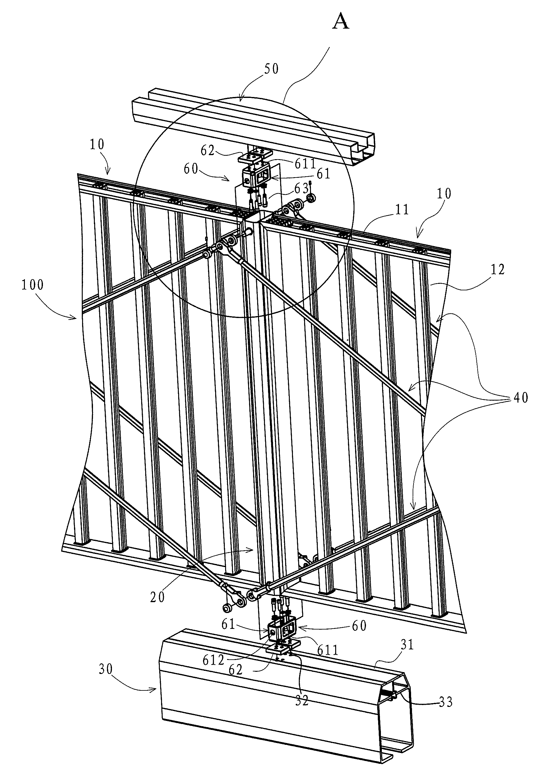
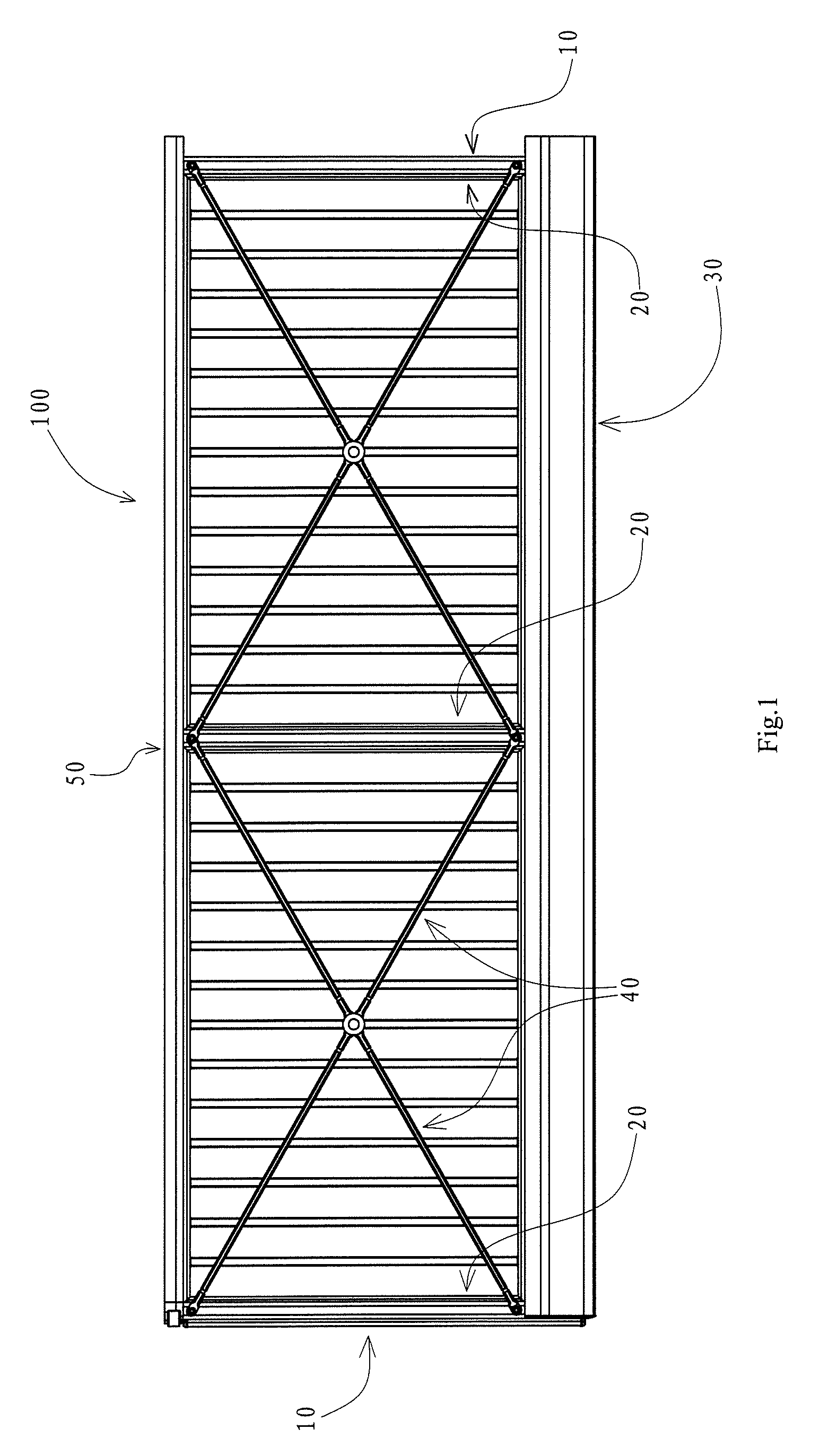
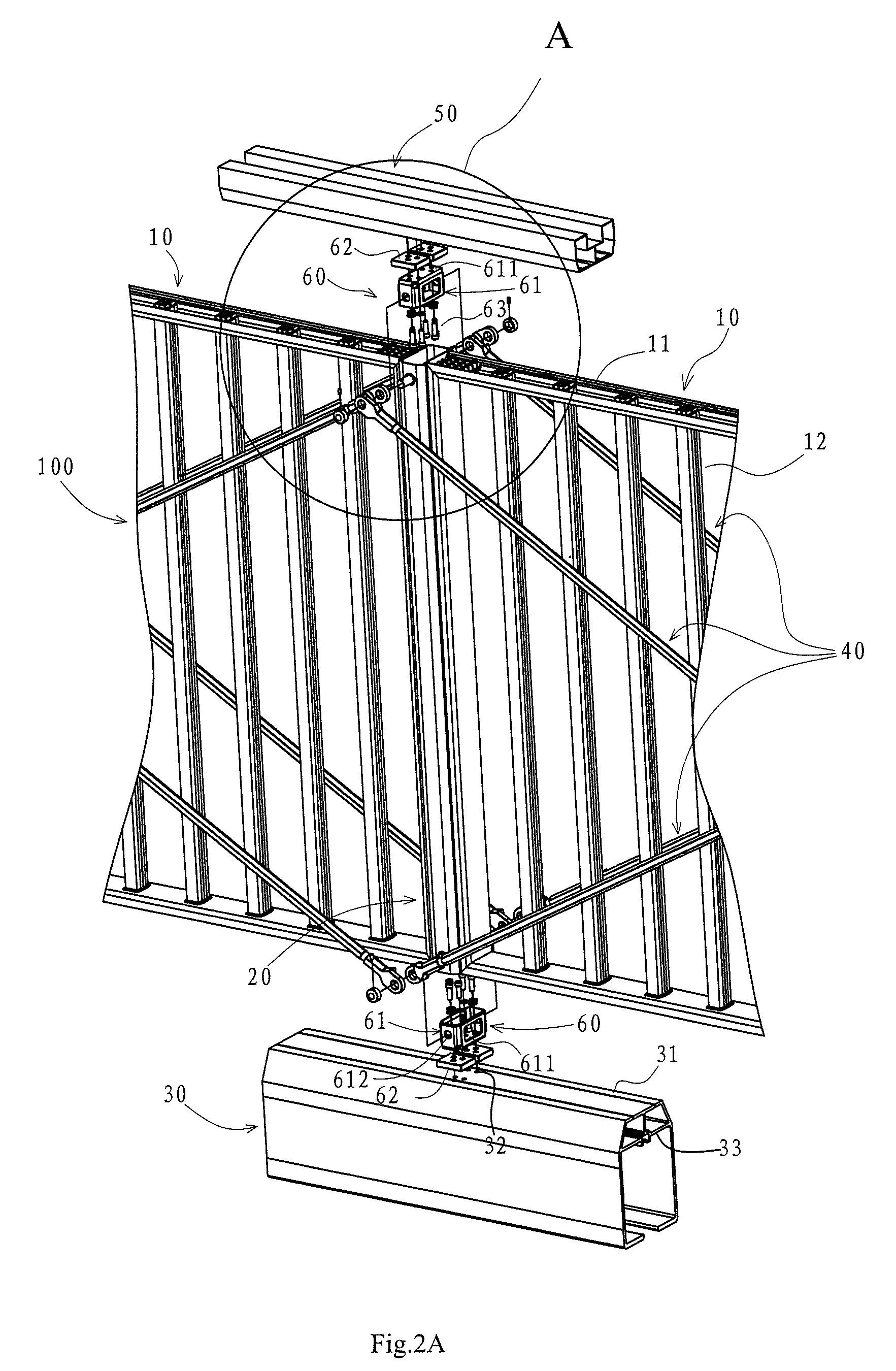
[0022]Referring to FIG. 1 and FIG. 2, the sliding door arrangement according to the present invention includes a plurality of door units 10, a plurality of upright posts 20, a lower beam 30, cross rod assemblies 40 and connectors 60. The sliding door arrangement may selectively include an upper beam 50. The door unit 10 is grid type, to be specific, the door unit 10 is a grid type part formed by connecting an outer frame 11 of aluminum profile and a plurality of vertical rods 12 of hollow aluminum tube which are arranged vertically and spaced apart from each other, and the door unit 10 can be packaged and transported separately. The sliding door arrangement 100 of the present invention is generally configured by connecting the door units by the plurality of the upright posts. Though only two door units are shown in FIG. 1 an...


PUM


Abstract

A sliding door arrangement includes a plurality of door units; at least one upright post connecting adjacent door units; a lower beam located at the bottom of and connected with the upright post; and a plurality of cross rod assemblies disposed at one side or both sides of the door units respectively to adjust the tightness of the sliding door arrangement. The sliding door arrangement of the present invention can be packaged and transported in separate parts and then quickly and conveniently assembled on site. In addition, the sliding door arrangement of the present invention is perfectly integral and decorative and provides sufficient strength.

Description

CROSS-REFERENCE TO RELATED APPLICATION[0001]This application claims the priority benefit of Chinese application serial no. 200810066257.1, filed Mar. 28, 2008. The entirety of the above-mentioned patent application is hereby incorporated by reference herein and made a part of specification.BACKGROUND OF THE INVENTION[0002]1. Field of the Invention[0003]The present invention relates to a sliding door which is opened or closed in an integrally sliding way, particularly relates to a door arrangement for a sliding door, which is convenient to transport and assembly, and which is perfectly integral and decorative.[0004]2. Discussion of the Related Art[0005]Doors are important component parts for buildings and public facilities. Doors are also the most frequently used architectural components. Common doors include doors opened pivotally, telescopic doors opened or closed telescopically as yard doors and sliding doors opened in a push-pull way as yard doors. Conventional sliding door consi...

Claims


Application Information

Patent Timeline
Patent Type & Authority Patents(United States)
IPC IPC(8): E04C2/38
CPCE06B11/045
Inventor YU, JIAHONG
Owner HONGMEN ADVANCED TECH CORP
Why Eureka
Try Eureka