Spraying device

a technology of a spraying device and a spraying tube, which is applied in the direction of cleaning processes and utensils, cleaning process and utensils, chemistry apparatus and processes, etc. it can solve the problems of low durability, inconvenient use, and parts replacement with increasing frequency, so as to improve the durability of the inner fluid transmission tube, prevent friction, and reduce friction

Active Publication Date: 2014-10-14
STRONG FORTRESS TOOL
View PDF4 Cites 10 Cited by
  • Summary
  • Abstract
  • Description
  • Claims
  • Application Information

AI Technical Summary

Benefits of technology

[0006]Therefore, it is an object of the present invention to provide a spraying device in which a friction force between the outer transmission tube and the inner transmission tube is low so as to improve the durability of the inner transmission tube and to reduce frequency of parts replacement.
[0015]Thereby, the inner fluid transmission tube does not directly contact with the outer fluid transmission tube but the friction reducing layer so as to prevent the friction between the inner fluid transmission tube and the fluid outer transmission. Further, the friction to the inner fluid transmission tube can be reduced by material and structure of the friction reducing layer, so that the durability of the inner fluid transmission tube is improved and frequency of parts replacement for the inner fluid transmission tube is reduced.
[0016]In additional, the friction reducing layer in an embodiment of the present invention is a tube, which is easy in manufacturing due to its simple structure. The friction reducing layer also has practicality in disposing because it can be assembled with the fluid outer transmission conveniently and quickly.

Problems solved by technology

In view of the above circumstances that the spraying gun in a conventional prior art has low durability, that results in parts replacement with increasing frequency and inconvenient in use.

Method used


Image

  • Spraying device
  • Spraying device
  • Spraying device

Examples


Embodiment Construction

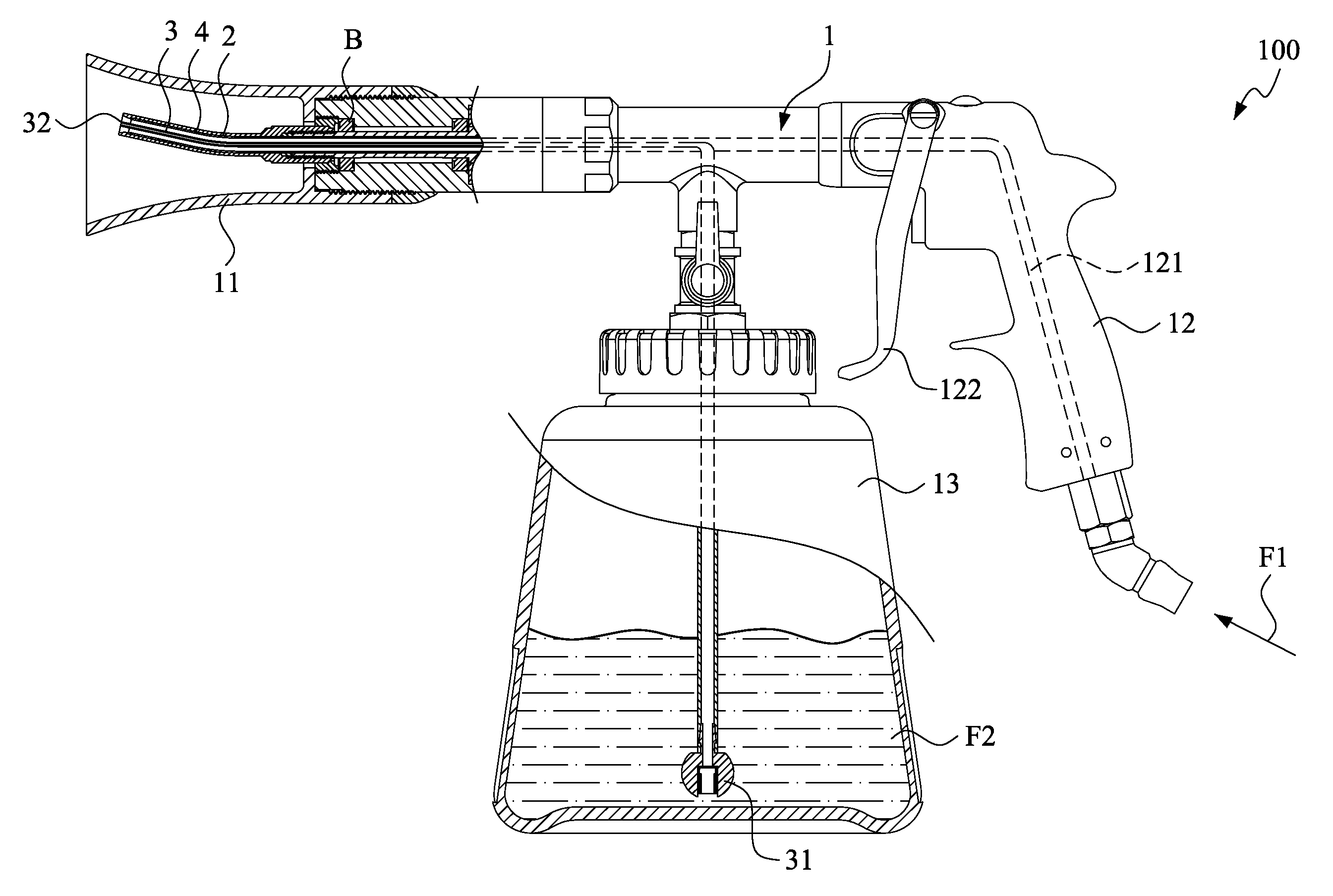
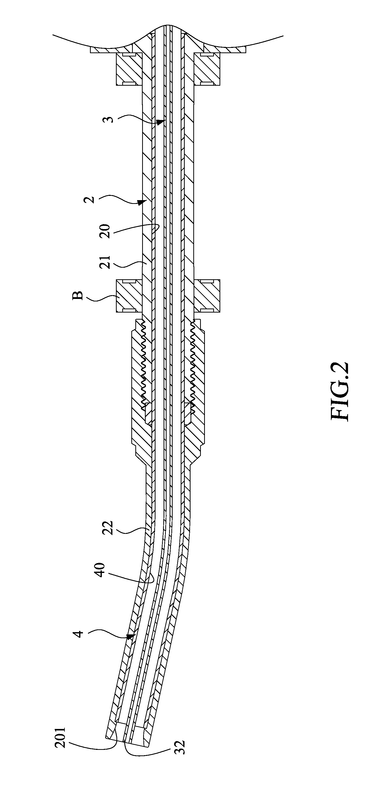
[0022]Please refer to FIGS. 1-3. FIG. 1 is a cross-section view of a spraying device according to an embodiment of the present invention, FIG. 2 is a partial enlarged view of FIG. 1, and FIG. 3 is a partial explosion diagram of FIG. 1.

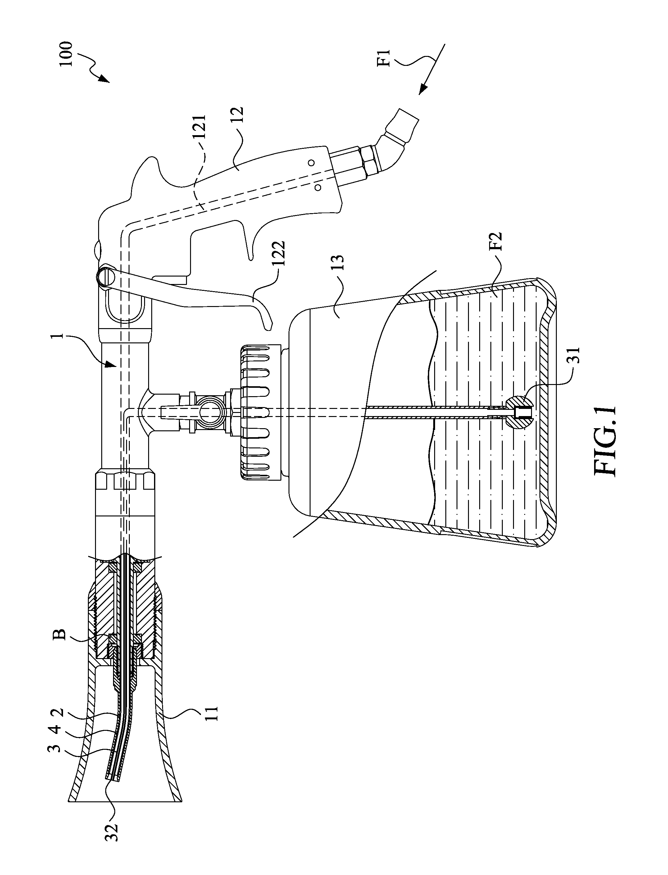
[0023]As shown in FIGS. 1-3, a spraying device 100 according to an embodiment of the present invention includes a body 1. The body is provided at one end thereof with a spraying head 11, the other end thereof with a control handle 12, and a lower portion thereof being assembled with a fluid container 13.

[0024]An outer fluid transmission tube 2, provided in the body 1, is assembled to the body 1 with a bearing B, so as to rotate with an axial of the spraying device 100. Certainly, there are many structures that enable the outer fluid transmission tube 2 to be rotatable with the body 1, for example, a structure in which the outer fluid transmission tube 2 is combined with a motor, a fan, or the like may be given.

[0025]The outer fluid transmission tube 2 ...


PUM


Abstract

A spraying device includes a rotatable outer fluid transmission tube and an inner fluid transmission tube disposed in the outer fluid transmission tube. A friction reducing layer, rotated together with the outer fluid transmission tube, is provided between the outer fluid transmission tube and the inner fluid transmission tube. The friction reducing layer is made of a material having a low friction coefficient and has a smooth inner wall surface, so as to make a friction force between the friction reducing layer and the inner fluid transmission tube lower and improve the durability of the inner fluid transmission tube.

Description

FIELD OF THE INVENTION[0001]The present invention relates to a spraying gun, and more particularly to a spraying device having a reduced friction force between an outer fluid transmission tube thereof and an inner fluid transmission tube thereof.BACKGROUND OF THE INVENTION[0002]Many spraying guns have been used widely for cleaning dust and dirt from a surface of an object, for watering, for spraying paint, and the like. The spraying guns remove dust and dirt by spraying a high pressure fluid, and perform watering and spraying paint with the use of a high pressure fluid mixed with water or other spraying liquid.[0003]In a conventional prior art, a high pressure fluid is introduced into the spraying gun and is then sprayed out from an outer transmission tube of the spraying gun. An inner transmission tube, which has a cross section area smaller than that of the outer transmission tube, is provided in the outer transmission tube. When the high pressure fluid is sprayed out of the outer...

Claims


Application Information

Patent Timeline
Patent Type & Authority Patents(United States)
IPC IPC(8): A62C13/62B05B1/26B05B3/06B05B7/24B08B3/02
CPCB05B7/2454B05B3/06B08B3/028B05B1/265B05B15/18
Inventor CHEN, CHIN-NAN
Owner STRONG FORTRESS TOOL
Why Eureka
Try Eureka