Stents with attached looped ends

a looped end and stent technology, applied in the field of stents, can solve the problems of difficult position adjustment of the deployed stent, particularly in the direction of the extension of the welded or twisted end termination, and present a risk of tissue damage, so as to facilitate the intraluminal delivery without the risk of surrounding tissu

Active Publication Date: 2005-03-03
BOSTON SCI SCIMED INC
View PDF99 Cites 146 Cited by
  • Summary
  • Abstract
  • Description
  • Claims
  • Application Information

AI Technical Summary

Benefits of technology

[0022] While shown and described primarily with braided and wound tubular structures, end closure members in accordance with the present invention can be employed to enhance virtually any open-frame structure having strand couplings at one of its ends, to render that end more flexible and reduce the risk of trauma to surrounding tissue.
[0025] Thus in accordance with the present invention, a stent or other open-frame prosthesis is fashioned with flexible, blunt, atraumatic ends, so that after its deployment in a body lumen, the device is movable without the risk of injury to surrounding tissue. As compared to similarly sized devices with conventional looped end construction, devices constructed according to the invention are compressible radially into smaller diameters to facilitate their intraluminal delivery. The looped end terminations described herein can be formed at either end or both ends of stents and other open-frame prostheses.

Problems solved by technology

In any event, while these stents are well suited for a variety of procedures, the welded or twisted end terminations are disadvantageous.
Because of the abrupt ends of the welded or twisted end terminations, the poking occasioned by their relative stiffness presents a risk of damage to tissue.
Consequently, any positional adjustment of a deployed stent, particularly in the direction that the welded or twisted end terminations extend, is difficult.
Another problem encountered with the twisted or welded end terminations is that adjacent twisted wire pairs may interlock when the stent is radially compressed into the delivery state, and then interfere with radial expansion of the stent at a treatment site.
While they are reduced, these difficulties remain, most notably to prevent any substantial proximal repositioning of a deployed stent.
Further, even the looped distal end of such device presents a problem that can limit its use.

Method used


Image

  • Stents with attached looped ends
  • Stents with attached looped ends
  • Stents with attached looped ends

Examples


Embodiment Construction

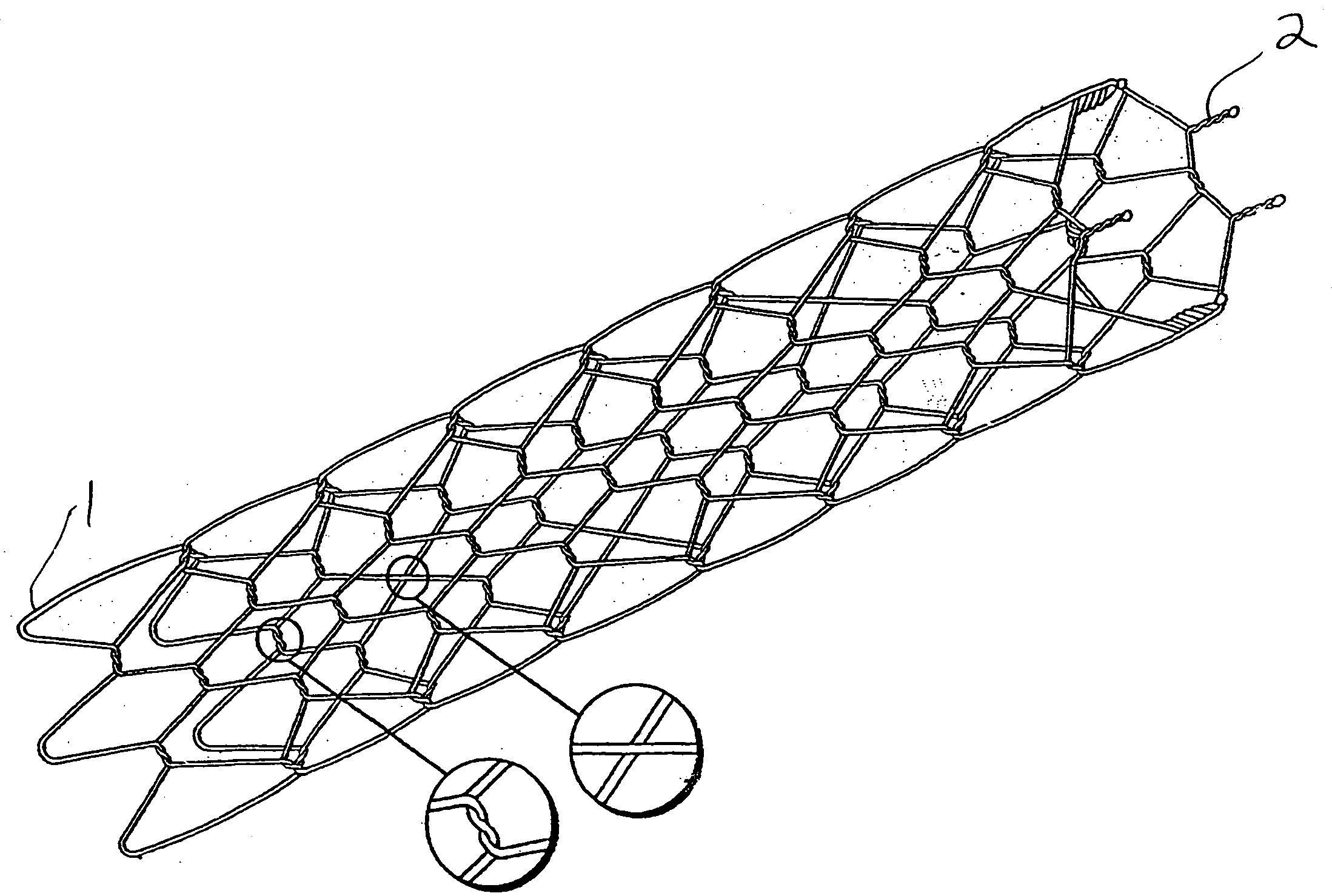
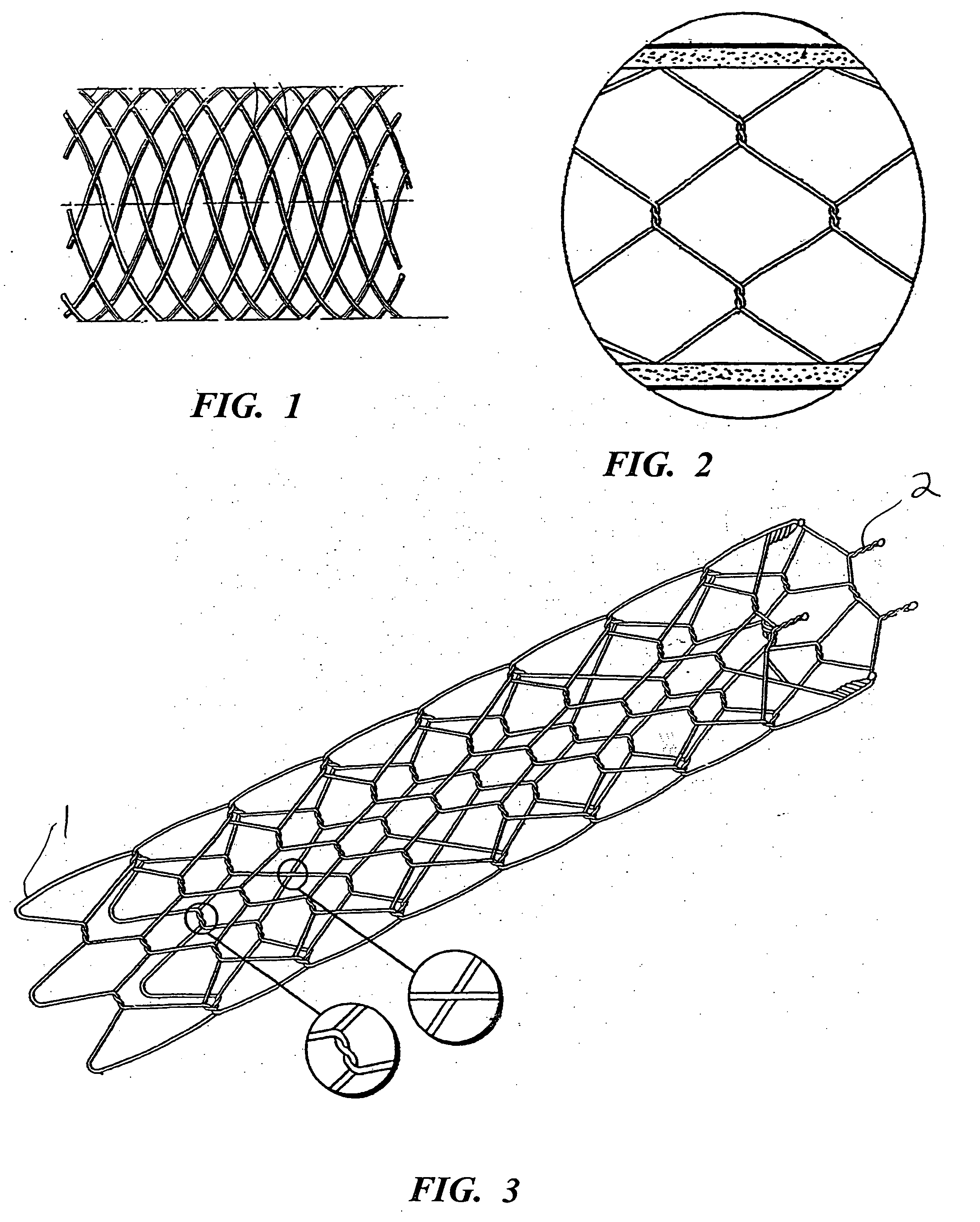
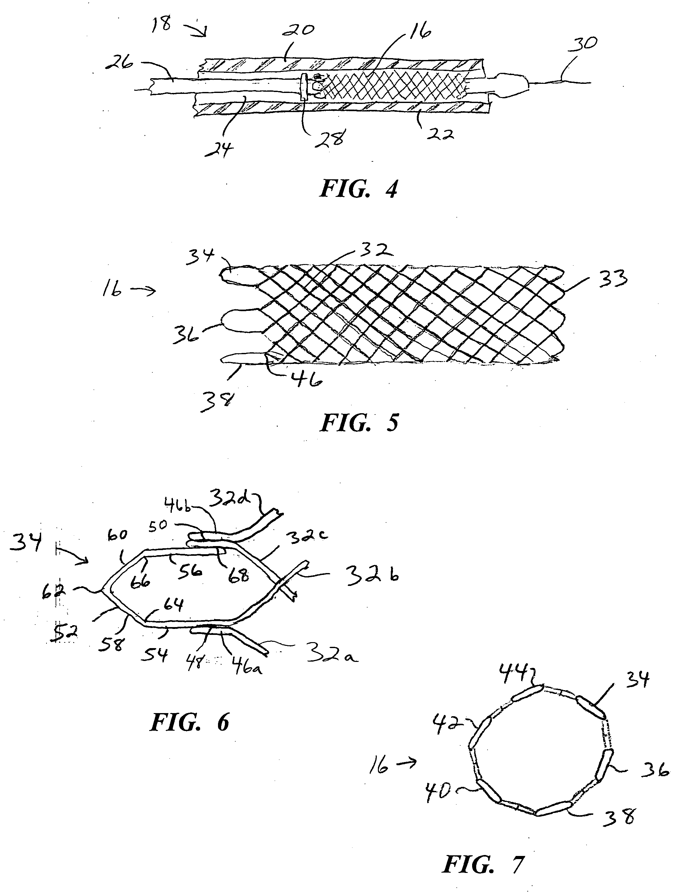
[0037] Turning now to the drawings, there is shown in FIG. 1 a stent 16 fabricated according to the present invention, and part of a device 18 used to intraluminally deliver the stent to an intended treatment site and deploy the stent at the treatment site.

[0038] The device includes an elongate, flexible outer catheter 20 having a distal end region 22, along which the outer catheter surrounds stent 16 and maintains the stent in a reduced-radius, axially elongated delivery state to facilitate an intraluminal delivery of the stent to the treatment site.

[0039] Stent 16 is contained within a lumen 24, which runs substantially the entire length of the outer catheter. An inner catheter 26, contained in the lumen, extends lengthwise along the outer catheter and is moveable axially relative to the outer catheter. A deployment member 28 is fixed to inner catheter 26, proximally of stent 16. Inner catheter 26 includes a lumen (not shown) to accommodate a guidewire 30, which is used to guide...


PUM

PropertyMeasurementUnit
lengthaaaaaaaaaa
shapeaaaaaaaaaa
external stressaaaaaaaaaa

Abstract

An open frame prosthesis is formed with looped end terminations at its proximal and distal ends. At one end of the prosthesis, the filaments or strands are welded together in pairs to form strand couplings. A plurality of loop segments are connected to the strand couplings, one loop segment for each pair of adjacent strand couplings. In one version of the prosthesis, strands at the opposite end are bent to form looped ends. In another version, loop segments are connected to pairs of strand couplings at both ends of the prosthesis. The loop segments can be connected to the couplings by welding, fusion bonds, or tubes, which are either crimped or heat shrunk.

Description

[0001] This application claims the benefit of U.S. Provisional Application No. 60 / 472,929 entitled “Stents With Welded Looped Ends,” filed May 23, 2003.BACKGROUND OF THE INVENTION [0002] The present invention relates to stents and other body insertable devices of open frame construction, and more particularly to radially expandable or radially self-expanding prostheses. [0003] A variety of treatment and diagnostic procedures involve the use of devices intraluminally implantable into the body of the patient. Among these devices are stents, such as disclosed in U.S. Pat. No. 4,655,771 (Wallsten). This type of prosthesis, shown in FIG. 1, is a tubular, braided structure formed of thread elements wound helically in opposite directions. The stent is shown in a relaxed state, i.e. in the configuration assumed when the stent is subject to no external stress. The stent is elastically compressible to a reduced-radius, axially elongated state to facilitate an intraluminal delivery of the sten...

Claims


Application Information

Patent Timeline
Patent Type & Authority Applications(United States)
IPC IPC(8): A61F2/88A61F2/90
CPCA61F2/90A61F2002/9534D04C1/06A61F2/88D04C3/48Y10T29/49906A61F2230/0013A61F2230/0017Y10T29/49908Y10T29/49863D10B2509/06
Inventor LEANNA, GARY J.NORTON, PAUL K.BRADY, PETERMOLLOY, DEANZUPKOFSKA, MICHAEL E.
Owner BOSTON SCI SCIMED INC
Why Eureka
Try Eureka