Apparatus and method for lining in situ pipe

a technology of in situ pipelines and apparatus, applied in mechanical apparatus, pipe elements, fluid removal, etc., can solve the problems of deteriorating pipe sections, affecting the lifespan of the pipe, and excavation of pipelines or pipes, so as to improve the preparation of the bore

Inactive Publication Date: 2005-03-10
GOSS CHRIS
View PDF23 Cites 14 Cited by
  • Summary
  • Abstract
  • Description
  • Claims
  • Application Information

AI Technical Summary

Benefits of technology

[0012] Preferably, the guide tube is curved for aligning a liner which is supplied at an angle to the existing pipe, and more preferably extends along a path between the pipe, exposed in an excavation, to an elevation above the excavation. The guide tube preferably has a linear portion adjacent the pipe for the insertion of inflexible elements such as a bullet for connection to the leading end of the flexible liner. The bullet enables improved preparation of the bore of the pipe before insertion of the flexible liner following the bullet.

Problems solved by technology

Pipelines which carry fluids are susceptible to deterioration, corrosion and other conditions which seriously affect the lifespan of the pipe.
Excavation of a pipeline or pipe, to replace sections that have deteriorated, is costly and often detrimental to the environment.
In situ pipelines of pipe typically build corrosion and scale on an inner surface, over time.
Large pipes can be cleared using pigging techniques, however smaller diameter pipes do not lend themselves to this type of cleaning technique.
Due to the unwieldy lengths of liner that are required, the supply of liner is provided at surface and must be fed into the excavation down into the bore of the pipe.
Due to the angle of the minimal excavation and the usual horizontal plane of the in situ pipe, the orientation and insertion of inflexible liners presents a challenge.
Particularly when a large axial force is required to advance the liner, difficulties in handling are increased due to the flexibility of this type of liner—its is difficult to push a rope.
Further, the composite nature of the liner does not permit overly rough handling.

Method used


Image

  • Apparatus and method for lining in situ pipe
  • Apparatus and method for lining in situ pipe
  • Apparatus and method for lining in situ pipe

Examples


Embodiment Construction

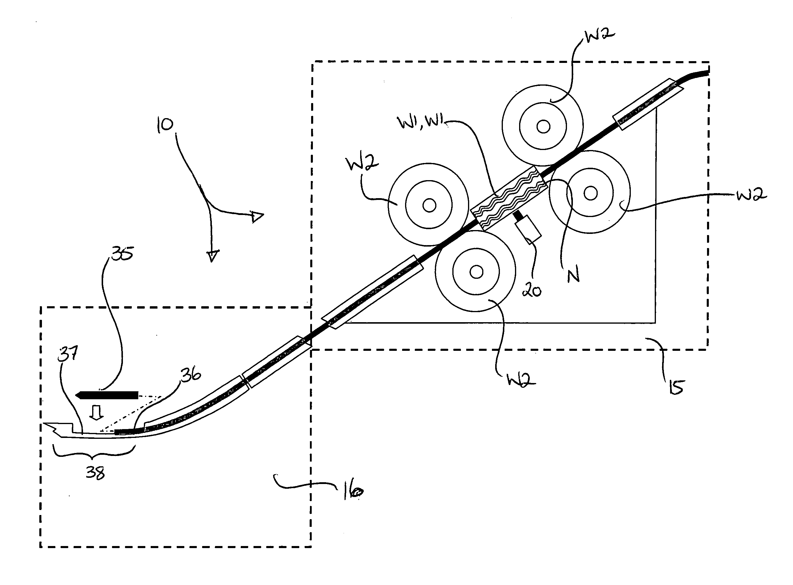
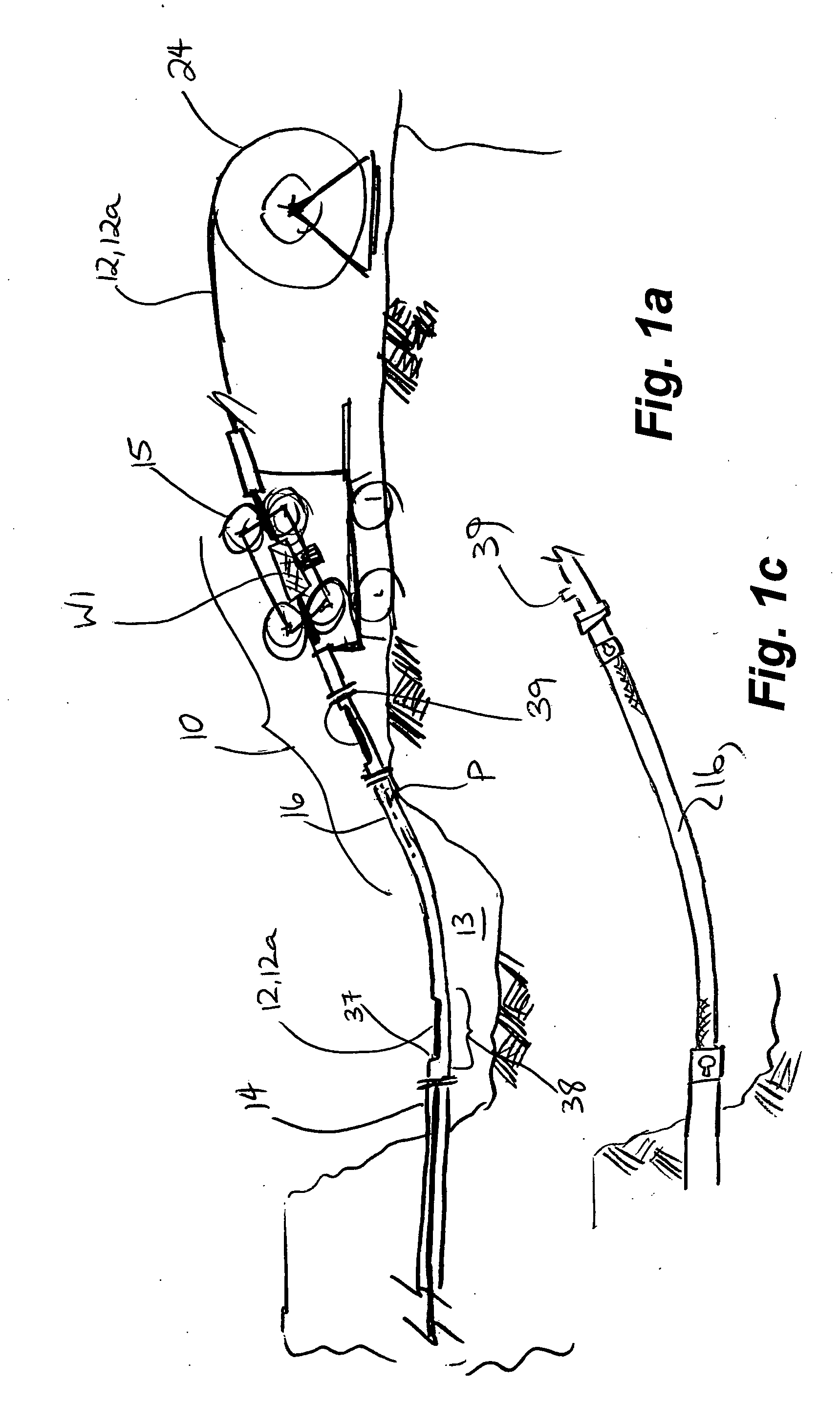
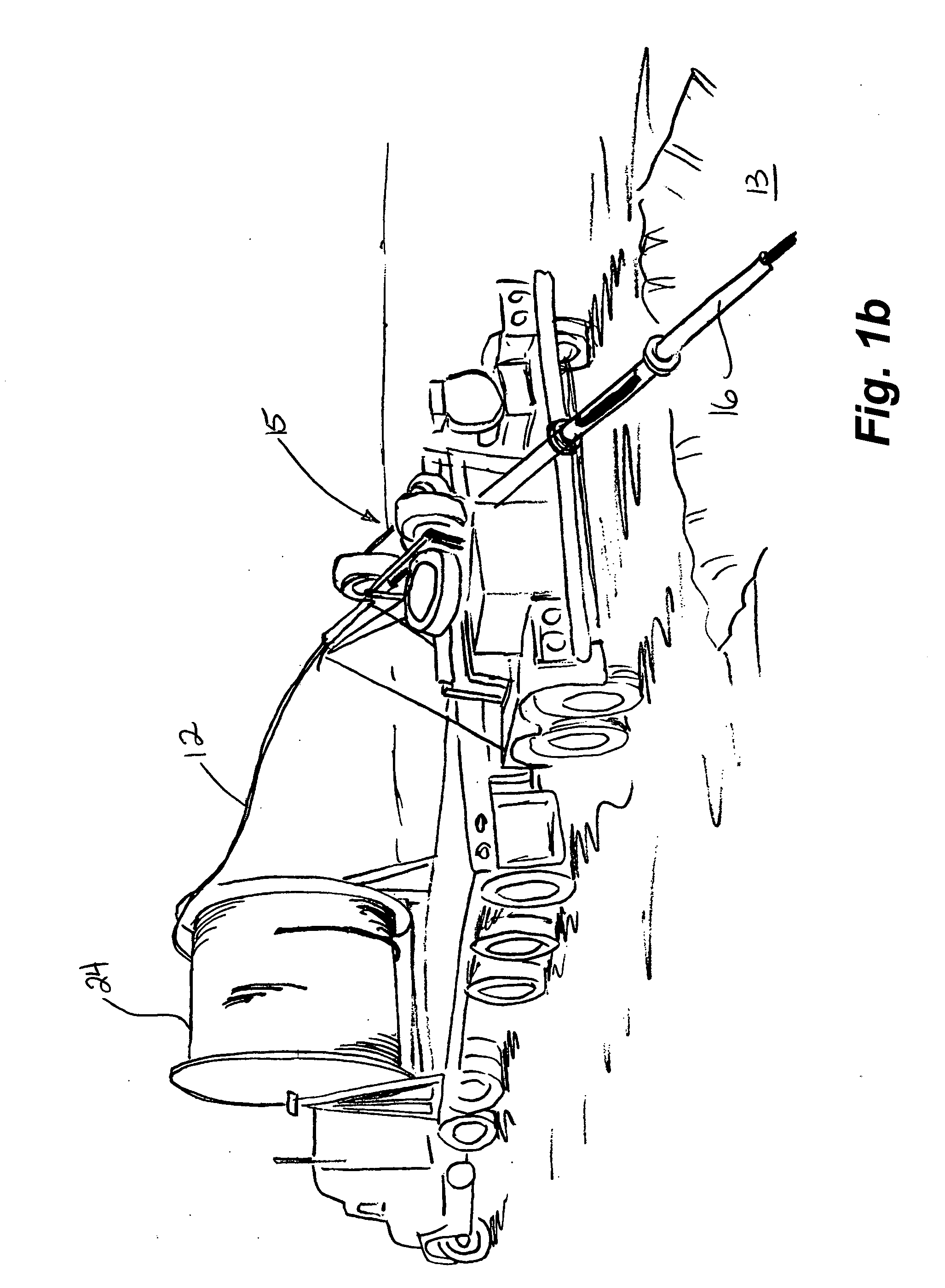
[0023] Having reference to FIG. 1a, apparatus 10 is provided to frictionally drive a flexible liner 12 from an elevation above an excavation 13, into and through an exposed end of an in situ pipe 14, located at a lower elevation such as adjacent a bottom of the excavation 13. The apparatus 10 comprises drive means 15 and a guide tube 16 extending between the drive means 15 and the pipe 14. The drive means 15 need not be aligned with the pipe 14.

[0024] The drive means 15 provides sufficient thrust to advance the flexible liner 12 through the guide tube 16 and through the pipe 14. The guide tube 16 is sufficiently rigid to elastically direct the liner through the guide tube between the drive means 15 and the pipe 14.

[0025] Generally, a flexible continuous composite line pipe is typically 2 inch diameter from FIBERSPAR® LinePipe™ from Fiberspar Corporation, suitable to line 4 inch diameter pipe 14.

[0026] Best seen in FIGS. 2, 3 and 4, the drive means 15 comprise at least a first pai...


PUM


Abstract

Apparatus for driving a flexible composite liner into an existing pipe in an excavation comprises contra-rotating wheels for driving flexible liner therebetween and into a guide tube extending between the driving wheels and the existing pipe. The guide tube forms a curved path to align the liner with the existing pipe. A port is formed in a linear portion of the guide tube enables insertion and connection of an optional inflexible bullet to the leading end of the flexible liner. The drive wheels are preferably assisted by transverse guide wheels. The existing pipe is exposed in an excavation. A trailer with the drive wheels is positioned adjacent the excavation, a guide tube is installed to extend between the trailer and the existing pipe forming a curved path, a spool of flexible liner is provided and driven through the guide tube to be aligned with and inserted into the existing pipe.

Description

FIELD OF THE INVENTION [0001] The present invention relates to apparatus and methods for remediation of in situ existing pipelines and more particularly to inserting a flexible fiberglass-reinforced composite liner into an existing pipeline. BACKGROUND OF THE INVENTION [0002] Pipelines which carry fluids are susceptible to deterioration, corrosion and other conditions which seriously affect the lifespan of the pipe. Excavation of a pipeline or pipe, to replace sections that have deteriorated, is costly and often detrimental to the environment. [0003] In situ pipelines of pipe typically build corrosion and scale on an inner surface, over time. The buildup within the pipe bore acts as a barrier to insertion of the liner. Large pipes can be cleared using pigging techniques, however smaller diameter pipes do not lend themselves to this type of cleaning technique. U.S. Pat. No. 4,827,553 to Turpin Sr. et al teaches passing a pipeline scraper into the bore of a pipeline and reciprocating ...

Claims


Application Information

Patent Timeline
Patent Type & Authority Applications(United States)
IPC IPC(8): F16L55/165F16L55/18
CPCF16L55/18F16L55/165
Inventor GOSS, CHRIS
Owner GOSS CHRIS
Why Eureka
Try Eureka