Uninterruptible power supply circuit having hot swappable battery module

Inactive Publication Date: 2005-03-10
DIGIPOWER MFG
11 Cites 43 Cited by

AI-Extracted Technical Summary

Problems solved by technology

However, due to a very long power line and a complex power network for supplying the commercial AC power to the computer, the commercial AC power is very sensitive to many variations such as under-voltage, over-voltage, inruch, noise, distorted waveform, frequency variation, etc, which severely impair the power stability and quality.
In particular, for a computer which requests high stability, sudden variations may lead to damage, crash or even breakdown of the computer.
The service cost thereof is unexpectedly high accordingly.
On the other hand, although the failure of hardware can be overcome by means of maintenance or replacement of components, the lost data s...

Method used

[0035] wherein when the commercial AC power is inputted, the UPS power supply circuit A activates the AC detecting and charging circuit 2 by means of the UPS controlling and circuit managing system 4, when the supply of the commercial AC power is normal, the battery detecting circuit 5 transmits a signal to the AC detecting and charging circuit 2, thereby detecting and charging the backup battery 7, when the charging operation is completed, the AC detecting and charging circuit 2 automatically interrupts the operation of the charging circuit, thereby avoiding damage of the backup battery 7 due to saturation of the backup battery 7; the UPS controlling and circuit managing system 4 transmits a signal to the AC detecting and charging circuit 2, and the AC detecting and charging circuit 2 is connected to the external connector 11 of the power supply circuit B via the internal connector 1, thereby detecting anytime whether the supply of the commercial AC power is normal, when the supply of the commercial AC power is abnormal, by means of the DC TO DC boosting circuit 3, the UPS power supply circuit A instantly uses the power of the backup battery 7 to provide a stable current to the power supply circuit B via the internal connector 1, thereby instantly providing ...

Benefits of technology

[0011] Another object of the invention is to provide an improved uninterruptible power supply circuit having a hot swappable battery module, in which the...

Abstract

An improved uninterruptible power supply circuit having a hot swappable battery module is connected with internal connectors of a UPS power supply circuit via external connectors of the power supply circuit. When the supply of the commercial AC power is abnormal, the backup battery provides power to the power supply circuit via the internal connectors in response to signals from the UPS power supply circuit, thereby instantly providing power to the computer and avoiding power interruption, wherein the backup battery is provided in a removable battery box, and several backup batteries can be connected in parallel by means of the removable battery box so as to provide power to the computer in case of long-term power failure.

Application Domain

Batteries circuit arrangementsElectric power +1

Technology Topic

AC powerExternal connection +4

Image

  • Uninterruptible power supply circuit having hot swappable battery module
  • Uninterruptible power supply circuit having hot swappable battery module
  • Uninterruptible power supply circuit having hot swappable battery module

Examples

  • Experimental program(1)

Example

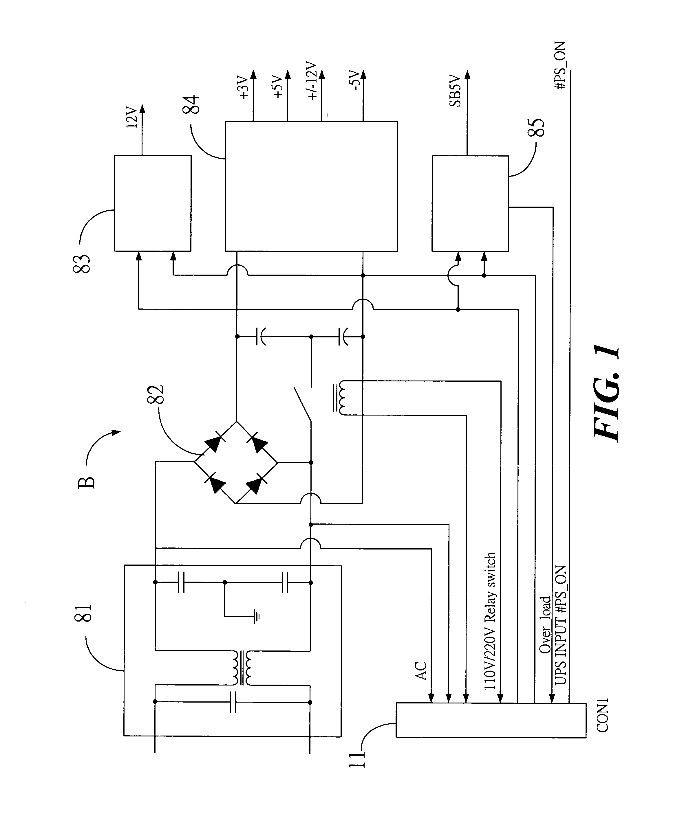
[0020]FIG. 1 illustrates an improved uninterruptible power supply circuit having a hot swappable battery module, wherein the power supply circuit B comprises essentially of:
[0021] a voltage regulator circuit 81, comprising at least a rectifier circuit 82 for accepting power, filtering and converting the power into a direct current to be outputted;
[0022] a DC TO DC converting circuit 84;
[0023] an external power 83;
[0024] a standby power 85;
[0025] a computer power switch 86; and
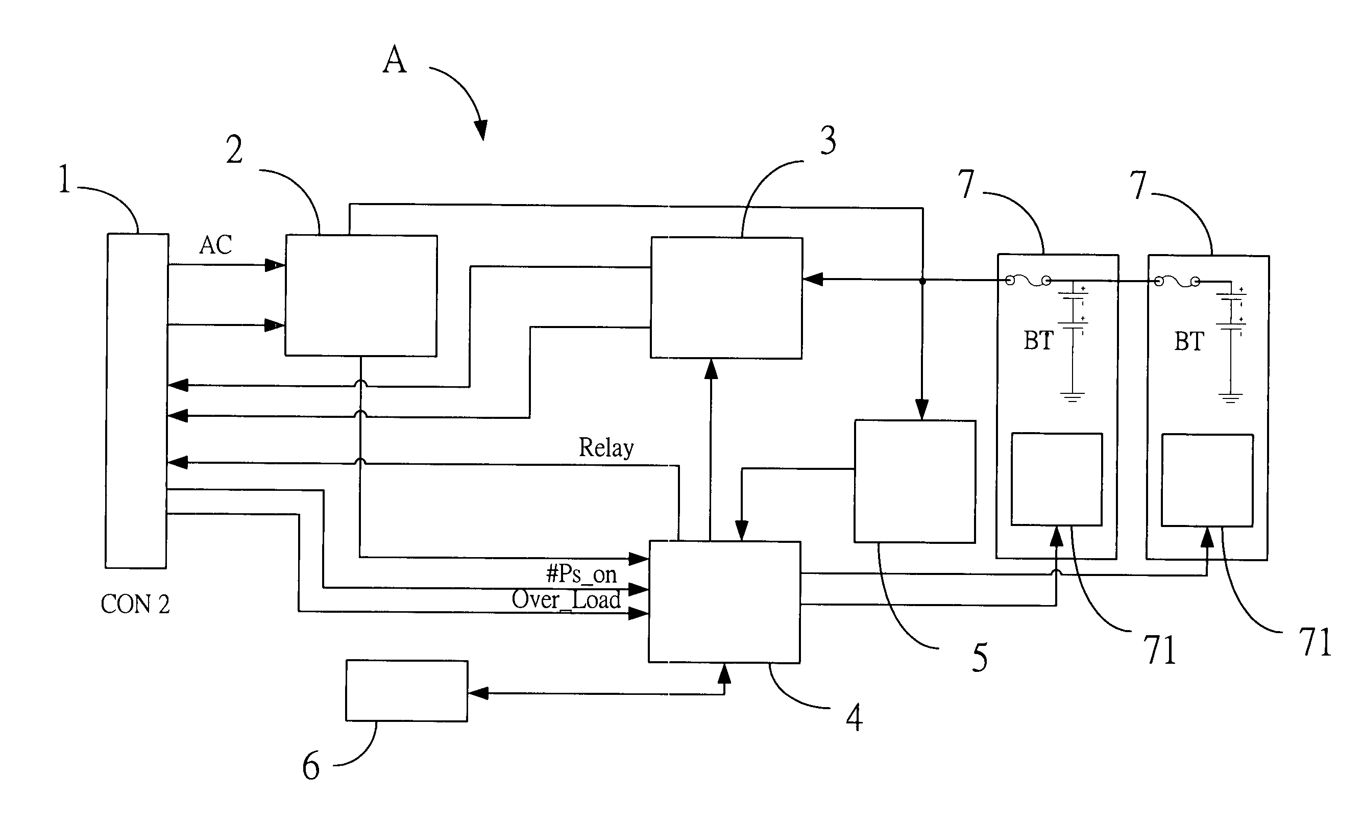
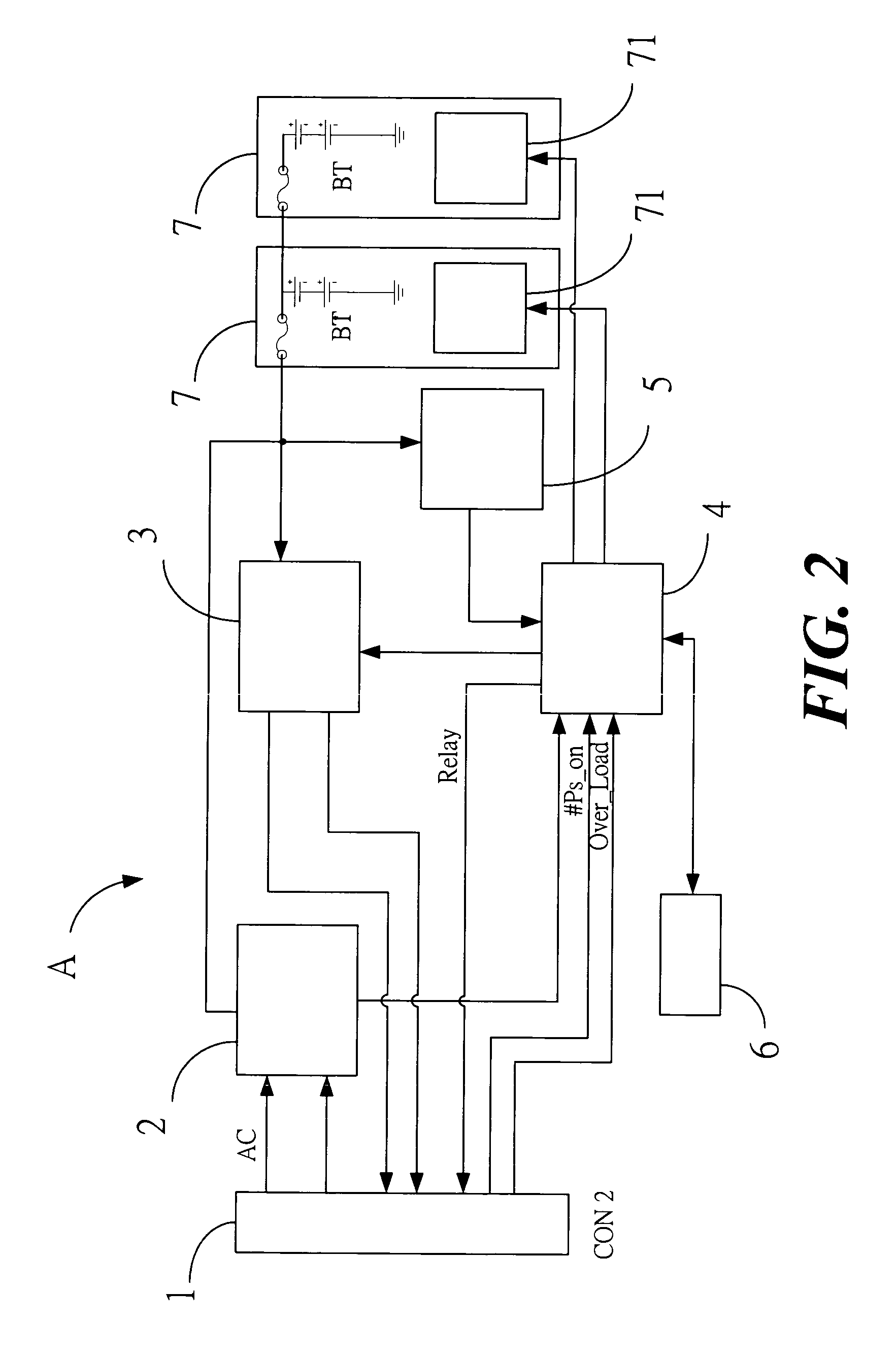
[0026] an external connector 11, connected to power supply signals, load signals, computer power switch 86 signals and relay switch signals, respectively, and connected with the internal connector 1 of the UPS power supply circuit A (FIG. 2), such that the UPS power supply circuit A realizes supply conditions of the commercial AC power via the internal connector 1. Accordingly, when the supply of the commercial AC power is abnormal, the UPS power supply circuit A can instantly provide power to the computer so as to maintain normal operation of the computer.
[0027]FIG. 2 illustrates an improved uninterruptible power supply circuit having a hot swappable battery module, wherein the UPS power supply circuit A comprises essentially of:
[0028] an internal connector 1, connected with the external connector 11 of the power supply circuit B;
[0029] an AC detecting and charging circuit 2, for detecting whether the supply of the commercial AC power is normal and charges to the backup battery 7 via the external connector 11;
[0030] a battery detecting circuit 5, for detecting whether the power of the backup battery 7 is sufficient, wherein when the power of the backup battery 7 is full, the charging circuit of the AC detecting and charging circuit 2 is switched off;
[0031] a backup battery 7, provided in a removable battery box 7A, wherein the backup battery 7 is charged by the AC detecting and charging circuit 2;
[0032] a monitoring signal 6, for displaying a control signal;
[0033] a DC TO DC boosting circuit 3, connected to the external connector 11 of the power supply circuit B via the internal connector 1, and instantly providing power to the voltage regulator circuit 81 when the supply of the commercial AC power is abnormal, thereby maintaining normal operation of the voltage regulator circuit 81;
[0034] a UPS controlling and circuit managing system 4, for controlling signals from the power supply circuit B, the UPS power supply circuit A and the removable battery box 7A;
[0035] wherein when the commercial AC power is inputted, the UPS power supply circuit A activates the AC detecting and charging circuit 2 by means of the UPS controlling and circuit managing system 4, when the supply of the commercial AC power is normal, the battery detecting circuit 5 transmits a signal to the AC detecting and charging circuit 2, thereby detecting and charging the backup battery 7, when the charging operation is completed, the AC detecting and charging circuit 2 automatically interrupts the operation of the charging circuit, thereby avoiding damage of the backup battery 7 due to saturation of the backup battery 7; the UPS controlling and circuit managing system 4 transmits a signal to the AC detecting and charging circuit 2, and the AC detecting and charging circuit 2 is connected to the external connector 11 of the power supply circuit B via the internal connector 1, thereby detecting anytime whether the supply of the commercial AC power is normal, when the supply of the commercial AC power is abnormal, by means of the DC TO DC boosting circuit 3, the UPS power supply circuit A instantly uses the power of the backup battery 7 to provide a stable current to the power supply circuit B via the internal connector 1, thereby instantly providing power to maintain normal operation of the computer.
[0036]FIG. 3 illustrates an improved uninterruptible power supply circuit having a hot swappable battery module, wherein the removable battery box 7A has therein the backup battery 7, and the removable battery box 7A is provided thereon with an inserting terminal, wherein a contact element extends from the front end of the inserting terminal, and the contact element is connected with the UPS power supply circuit A and provides the power to the computer by the UPS controlling and circuit managing system 4 of the UPS power supply circuit A, wherein the removable battery box 7A can be provided with a handle for facilitating drawing-out/installing the removable battery box 7A during the hot swapping operation. Furthermore, each of the bilateral sides of the removable battery box 7A can be provided with a gliding track for facilitating easily positioning and smoothly drawing-out/installing the removable battery box 7A during the hot swapping operation.
[0037]FIGS. 4 and 5 illustrate embodiments of an improved uninterruptible power supply circuit B having a hot swappable battery module. The power supply circuit B of the computer 9 is connected to one or more internal connectors 1 of the UPS power supply circuit A via the external connector 11, and they are connected in parallel so as to maintain normal operation in case of long-term power failure. Furthermore, another UPS power supply circuit A can be drawn out/installed in a hot swappable mode without switching off the computer 9, such that the battery of the computer 9 can be replaced without switching off the computer 9.
[0038] The improved uninterruptible power supply circuit having a hot swappable battery module, when comparing with other previous conventional technologies, has following advantages:
[0039] 1. The present invention uses connectors to connect the UPS power supply circuit and the power supply circuit, and uses the AC detecting and charging circuit to realize AC power conditions and instantly provides the power of the backup battery in case of abnormal power condition.
[0040] 2. The present invention uses connectors to connect the power supply circuit with one or more UPS power supply circuits so as to maintain normal operation in case of long-term power failure.
[0041] 3. By means of parallel connection and fault tolerance, the UPS power supply circuit is connected with at least one backup battery in parallel, and via power lines of the removable battery box in serial/parallel connection so as to expand shelf life thereof.
[0042] 4. By means of the parallel connection, the UPS power supply circuit and the removable battery box can be drawn out/installed without switching off the computer.
[0043] While the invention has been described in terms of what is presently considered to be the most practical and preferred embodiments, it is to be understood that the invention needs not be limited to the disclosed embodiment. On the contrary, it is intended to cover various modifications and similar arrangements included within the spirit and scope of the appended claims which are to be accorded with the broadest interpretation so as to encompass all such modifications and similar structures.
[0044] Many changes and modifications in the above described embodiment of the invention can, of course, be carried out without departing from the scope thereof. Accordingly, to promote the progress in science and the useful arts, the invention is disclosed and is intended to be limited only by the scope of the appended claims.

PUM

no PUM

Description & Claims & Application Information

We can also present the details of the Description, Claims and Application information to help users get a comprehensive understanding of the technical details of the patent, such as background art, summary of invention, brief description of drawings, description of embodiments, and other original content. On the other hand, users can also determine the specific scope of protection of the technology through the list of claims; as well as understand the changes in the life cycle of the technology with the presentation of the patent timeline. Login to view more.
Why Eureka
Try Eureka