Traceable patch cable and connector assembly and method for identifying patch cable ends

a patch cable and connector technology, applied in the direction of reradiation, coupling device connection, instruments, etc., can solve the problems of difficult and time-consuming, difficult to follow the physical cable from one point to the other, and easy so as to prevent damage to the cable, the effect of quick and easy identification

Inactive Publication Date: 2005-03-10
HON HAI PRECISION IND CO LTD
View PDF3 Cites 74 Cited by
  • Summary
  • Abstract
  • Description
  • Claims
  • Application Information

AI Technical Summary

Benefits of technology

[0006] A main object of the present invention is to provide a traceable patch cable having ends which can be quickly and easily identified while preventing damage to the cables.
[0007] A traceable patch cable used to transmit signals from one receptacle to another comprises a cable and two connectors attached to opposite ends of the cable. The cable comprises at least one electrical wire for transmitting signals and an optical fiber. The connectors each terminate an end of the electrical wire so that the electrical wire can be electrically connected to terminals in receptacles. Each connector forms an illuminating member thereon with a passage being defined in the illuminating member. Ends of the optical fiber are respectively terminated in the connectors under the illuminating members. Using a light beam shining through the passage at a first end of the cable, the light beam travels through the optical fiber to illuminates the illuminating member at a second end of the cable, thus making it easy to identify from among many cables.

Problems solved by technology

Often there are hundreds of cables which may even be tied together making it difficult to follow the physical cable from one point to the other.
Currently, labels and corresponding spreadsheets are often used, however, it is very difficult and time-consuming to identify the corresponding ends of cables from among hundreds of cables using their labels, and the cables can be easily damaged during the identification process.

Method used


Image

  • Traceable patch cable and connector assembly and method for identifying patch cable ends
  • Traceable patch cable and connector assembly and method for identifying patch cable ends
  • Traceable patch cable and connector assembly and method for identifying patch cable ends

Examples


Embodiment Construction

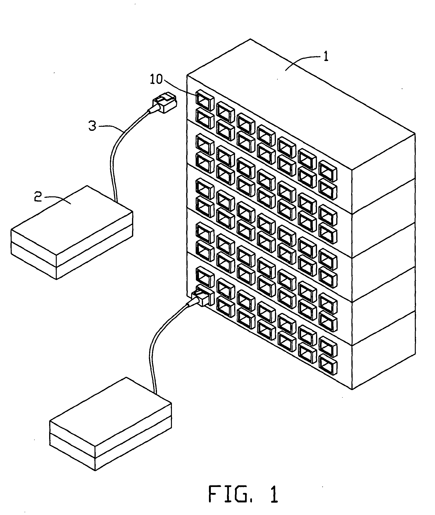
[0014] Referring now to the drawings in detail, FIG. I shows a connector assembly. The connector assembly comprises a patch panel 1, a plurality of terminals 2 (such as telephones or computers), and a plurality of traceable patch cables 3 each of which electrically connects the panel 1 and one terminal 2 for signal transmission therebetween. The panel 1 includes a plurality of receptacles 10, each of which is used to receive one end of a patch cable 3. The receptacles 10 are mounted in the panel 1 using suitable attaching means, such as screws or clasps. Each terminal 2 includes a receptacle (not shown) for accommodating the other end of the patch cable 3.

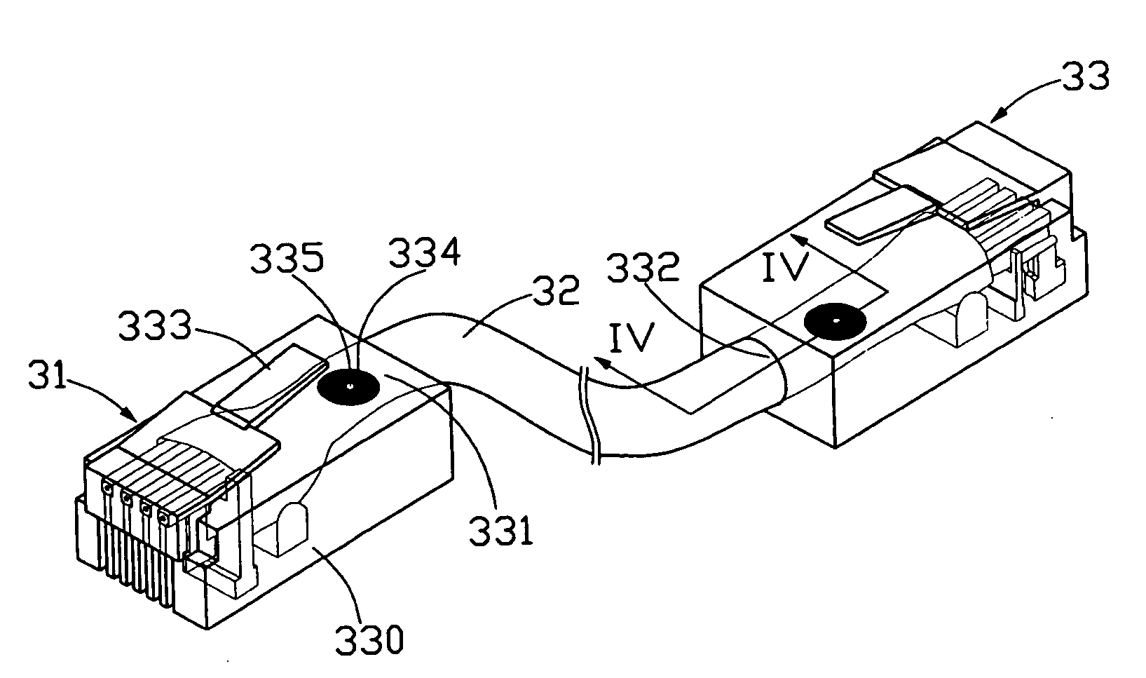
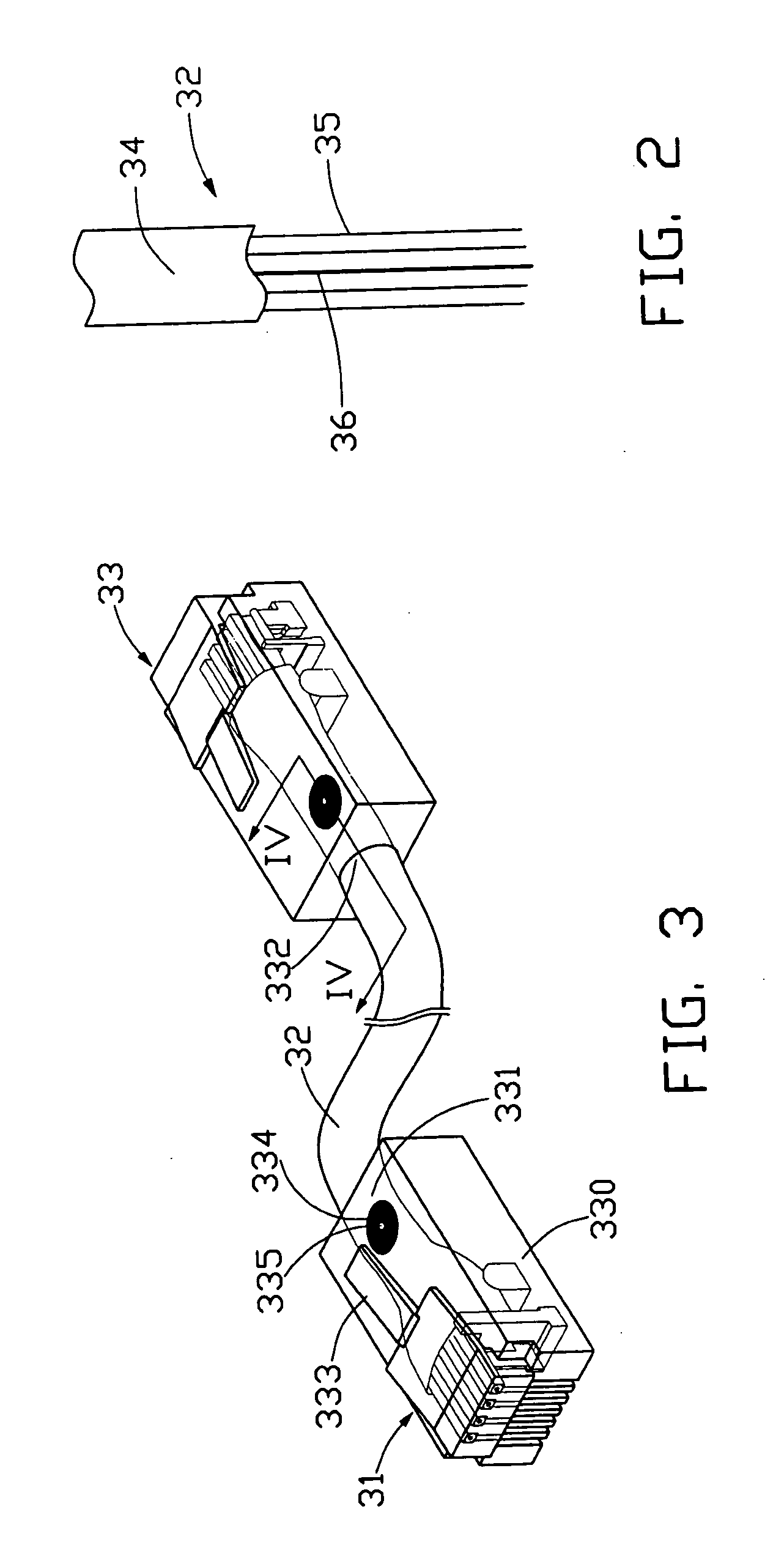
[0015] Referring to FIGS. 2 and 3 together, the patch cable 3 includes a cable 32 and two connectors 31, 33 disposed on opposite ends of the cable 3. The two connectors 31, 33 removably mate with a pair of receptacles which are respectively mounted in the panel 1 or a terminal 2. The cable 32 includes a jacket 34, a plurality of e...


PUM


Abstract

A traceable patch cable (3) used to transmit signals from one receptacle (10) to another comprises a cable (32) and two connectors (31, 33) attached to opposite ends of the cable. The cable comprises at least one electrical wire (35) for transmitting signals and an optical fiber (36). The connectors each terminate an end of the electrical wire so that the electrical wire can be electrically connected to terminals in receptacles. Each connector forms an illuminating member (334) thereon with a passage (335) being defined in the illuminating member. Ends of the optical fiber are respectively terminated in the connectors under the illuminating members. Using a light beam shining through the passage at a first end of the cable, the light beam travels through the optical fiber to illuminates the illuminating member at a second end of the cable, thus making it easy to identify from among many cables.

Description

BACKGROUND OF THE INVENTION [0001] 1. Field of the Invention [0002] The present invention relates to a system for identifying corresponding ends of patch cabling. [0003] 2. Description of Related Art [0004] In commercial settings and office buildings, patch panels in closets are used by technicians to route telephone lines or networking cables to different destinations. Sometimes one of the services fails and it becomes necessary to trace the cable, finding an origin and destination, to insure that nothing has been unplugged and to check any equipment between the origin and destination to isolate the point of failure (i.e. equipment malfunction, cable damage, and / or disconnects). Often there are hundreds of cables which may even be tied together making it difficult to follow the physical cable from one point to the other. Difficulties are frequently encountered if there is no means of absolute identification, To prevent disrupting service of a working line while tracing a non-workin...

Claims


Application Information

Patent Timeline
Patent Type & Authority Applications(United States)
IPC IPC(8): G01S13/00H01R11/11H01R13/66H01R24/58H01R31/06
CPCH01R24/62H01R13/7172
Inventor ANGELO, DEBORAH A.TSAI, NINGHOM, SONNY
Owner HON HAI PRECISION IND CO LTD
Why Eureka
Try Eureka