Multi-mode lighter

Inactive Publication Date: 2005-03-10
SOC DITE SOC BIC
View PDF72 Cites 17 Cited by
  • Summary
  • Abstract
  • Description
  • Claims
  • Application Information

AI Technical Summary

Benefits of technology

[0011] According to another exemplary embodiment of the present invention, the lighter may include a housing having a supply of fuel in communication with a nozzle, an ignition mechanism operable to create a spark to ignite the fuel proximate the nozzle, an actuating member extending from the housing and movable to release the fuel from the supply of fuel, and an inhibiting member extending from the housing and biased to a first position, wherein the inhibiting member is movable to a second position to resist, obstruct and/or prevent the ignition and/or the release of fuel from the nozzle. The lighter may further include an elastic element for biasing the inhibiting member to the first position. Additionally or alternatively, the lighter may include a conduit extending from the supply of fuel to the nozzle, and the fuel may be obstructed from flowing through at least a portion of the con

Problems solved by technology

Moving the inhibiting member a predetermined distance may resist, obstruct and/or prevent the actuating member from performing at least one step in igniting the fuel.
For example, moving the inhibiting member the predetermined distance may resist, obstruct and/or prevent the actua

Method used


Image

  • Multi-mode lighter
  • Multi-mode lighter
  • Multi-mode lighter

Examples


Embodiment Construction

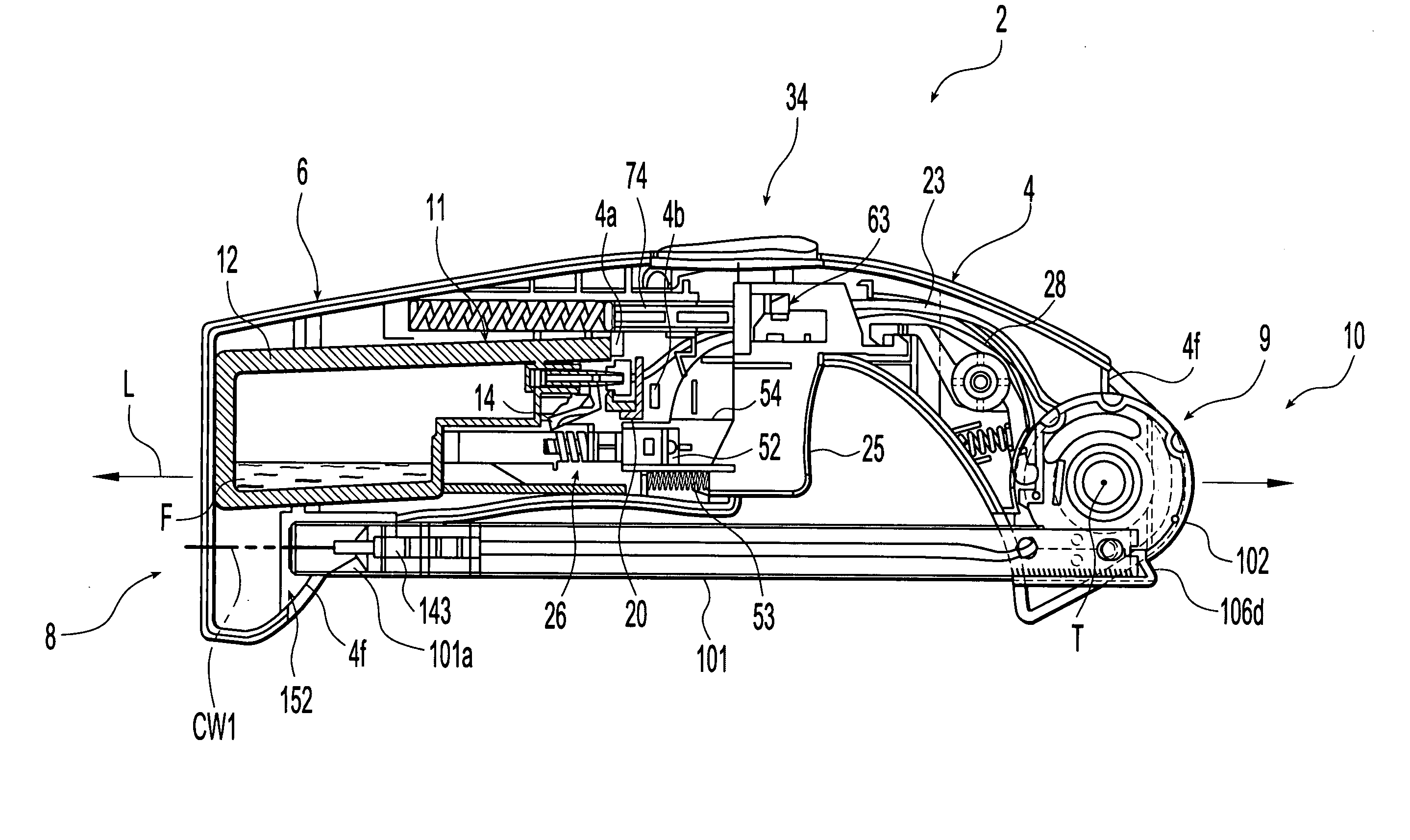
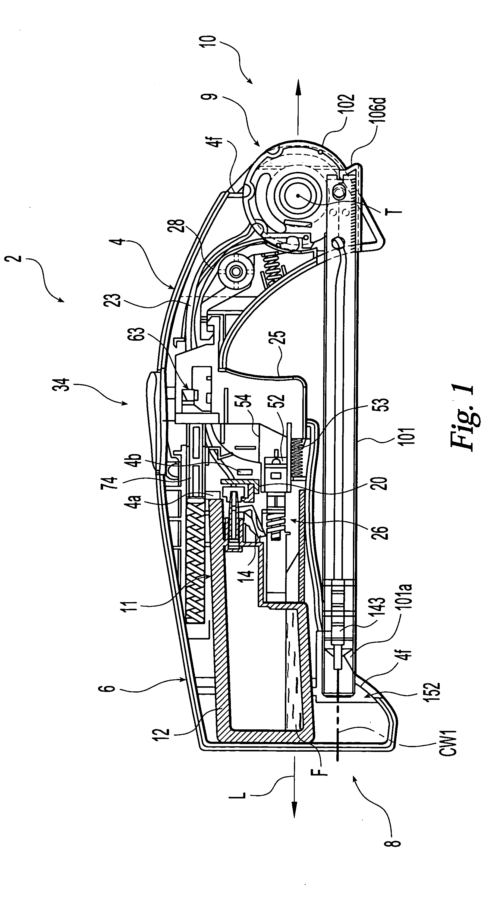
[0051] Turning to FIG. 1, an embodiment of a utility lighter 2 constructed in accordance with the present invention is shown with the understanding that those of ordinary skill in the art will recognize many modifications and substitutions which may be made to various elements. While the invention will be described with reference to a utility lighter, one of ordinary skill in the art could readily adapt the teaching to conventional pocket lighters and the like.

[0052] Lighter 2 generally includes a housing 4 which may be formed primarily of molded-rigid-polymer or plastic materials such as acrylonitrile butadiene styrene terpolymer or the like. The housing 4 may also be formed of two-parts that are joined together by techniques known by those of ordinary skill in the art, such as ultrasonic welding.

[0053] Housing 4 includes various support members, such as support member 4a discussed below. Further support members are provided in the lighter 2 for various purposes, such as supporti...


PUM


Abstract

The present invention is directed to a lighter including a housing having a supply of fuel, an actuating member extending from the housing and being movable to selectively perform at least one step in igniting the fuel, and an inhibiting member extending from the housing. Moving the inhibiting member a predetermined distance resists, obstructs and/or prevents the actuating member from performing at least one step in igniting the fuel. For example, moving the inhibiting member the predetermined distance may resist and/or prevent movement of the actuating member, may obstruct and/or prevent the release of fuel, and/or may resist and/or prevent the creation of a spark to ignite the fuel. Various other features which improve the functioning of the lighter may be provided separately or in combination.

Description

CROSS-REFERENCE TO RELATED APPLICATIONS [0001] The present application is a continuation-in-part of U.S. patent application Ser. No. 10 / 647,505, filed Aug. 26, 2003, which is a continuation-in-part of U.S. patent application Ser. No. 10 / 389,975, filed Mar. 18, 2003, which is a continuation-in-part of U.S. patent Ser. No. 10 / 085,045, now U.S. Pat. No. 6,726,469, filed Mar. 1, 2002, which is a continuation-in-part of both U.S. patent application Ser. No. 09 / 817,278 and U.S. patent application Ser. No. 09 / 819,021, now U.S. Pat. No. 6,488,492, both of which were filed on Mar. 27, 2001, and both of which are continuation-in-part applications of U.S. patent application Ser. No. 09 / 704,689, now U.S. Pat. No. 6,491,515, filed Nov. 3, 2000. The contents of these six applications are expressly incorporated herein by reference thereto.TECHNICAL FIELD OF THE INVENTION [0002] The present invention generally relates to lighters such as pocket lighters used to light cigarettes and cigars, or utili...

Claims


Application Information

Patent Timeline
IPC IPC(8): F23Q2/16
CPCF23Q2/287F23Q2/164
Inventor SGROI, ANTHONYUKLEJA, JEFFADAMS, PAUL
Owner SOC DITE SOC BIC
Why Eureka
Try Eureka