Joint structure

Active Publication Date: 2005-03-10
ARACO CORP
View PDF12 Cites 71 Cited by
  • Summary
  • Abstract
  • Description
  • Claims
  • Application Information

AI Technical Summary

Benefits of technology

The lock portion has an opposite side with three ribs formed on both widthwise ends and a substantially central portion thereof so as to respectively extend along an insertion direction of the lock portion. When the lock portion deforms the openin

Problems solved by technology

In such a case however, variations due to manufacturing parameters in the width of the lock claw 2 or locking m

Method used


Image

  • Joint structure
  • Joint structure
  • Joint structure

Examples


Example

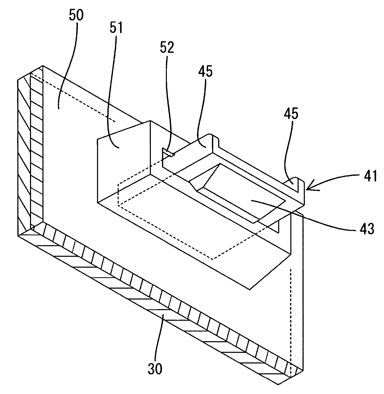
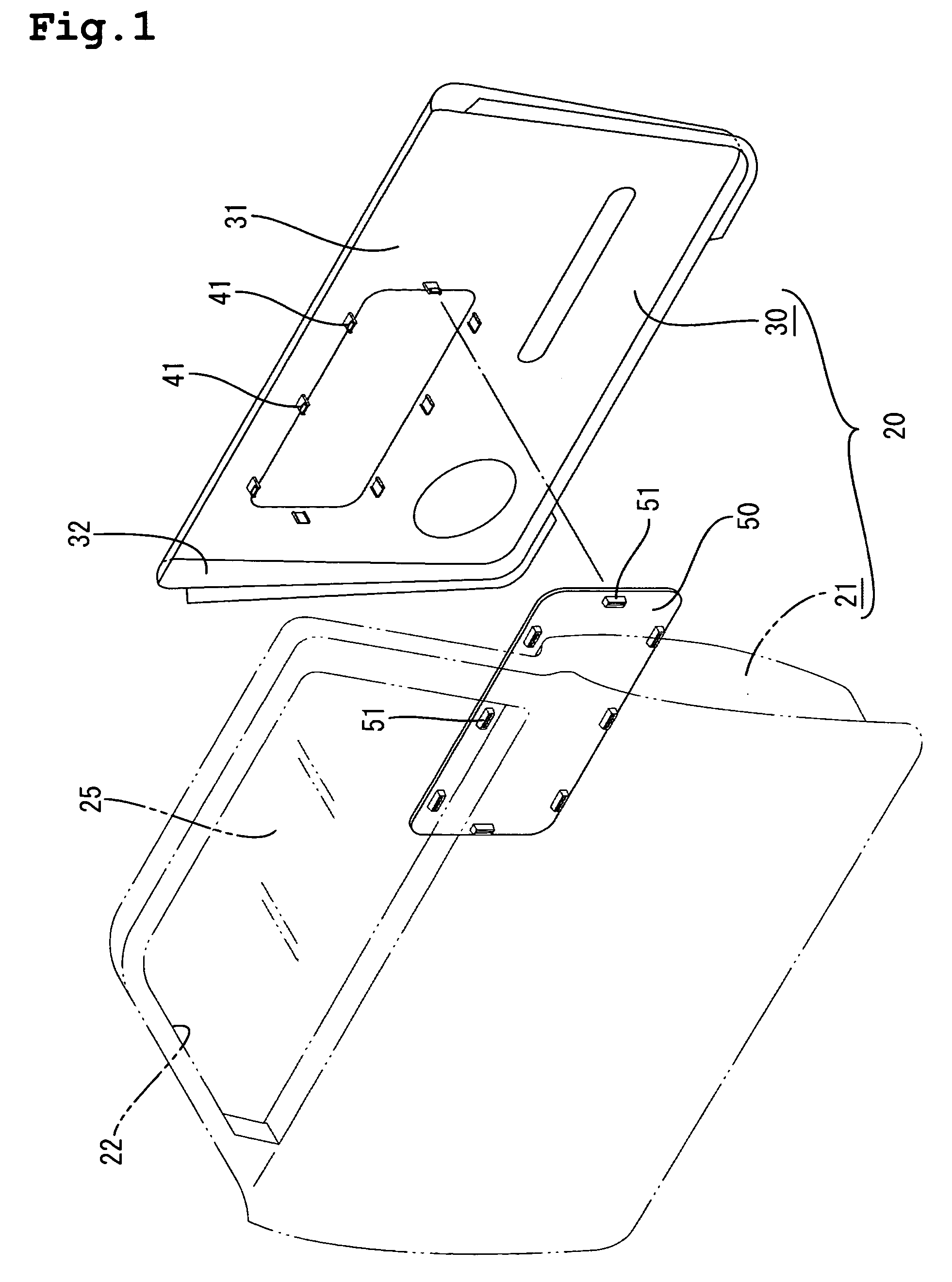
Several embodiments of the present invention will be described with reference to FIGS. 1 to 14. The coupling structure for connecting members is applied to a side door 20 of an automobile in a first embodiment. Referring to FIG. 1, reference numeral 21 designates a metallic door panel hingedly mounted on a body of an automobile (not shown) so as to be closed and opened. The door panel 21 is formed into a configuration conforming to the outer dimensions of the body. A window frame 22 is open at an upper half of the door panel 21. A window glass 25 configured so as to fit within the window frame 22.

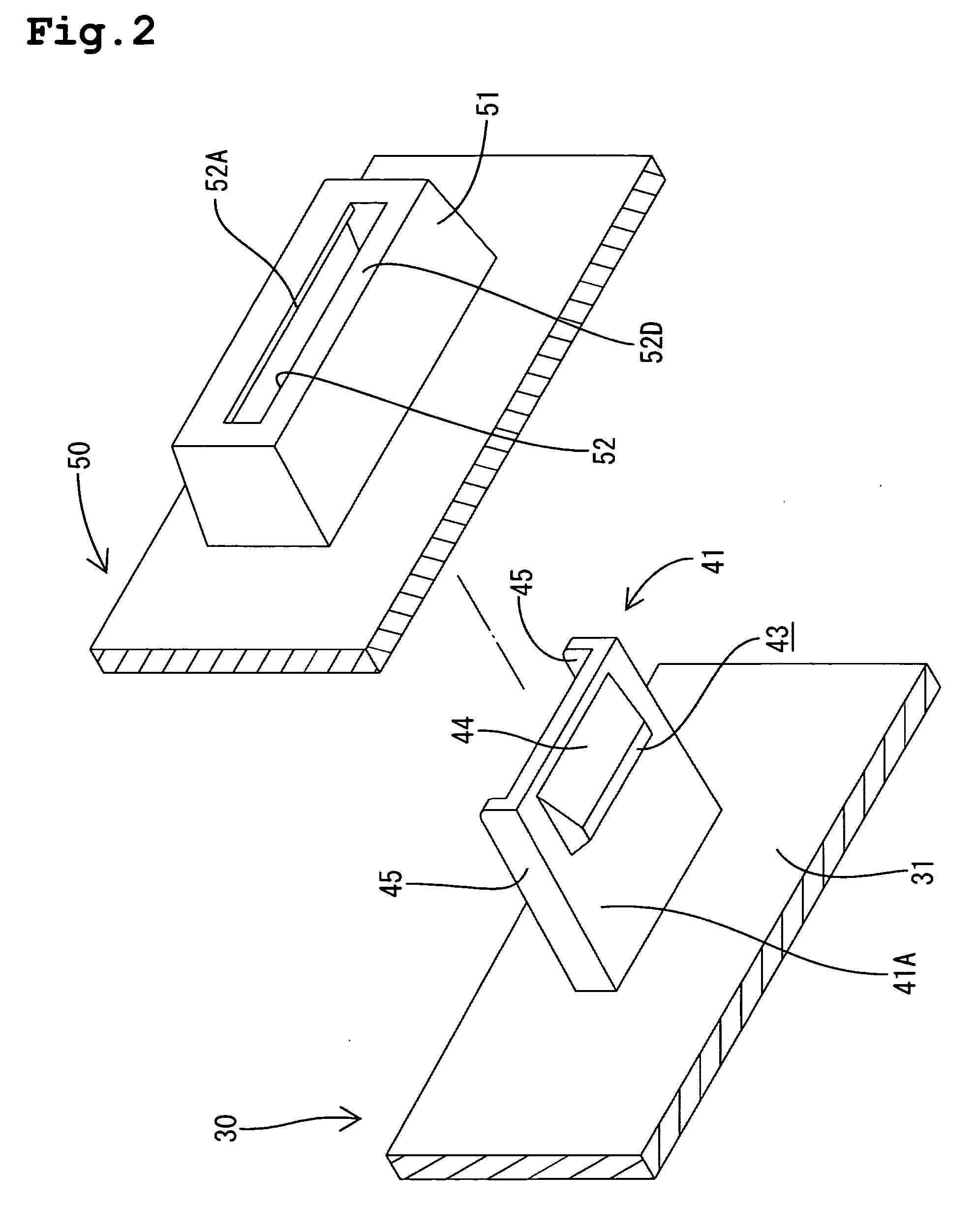
The door trim 30, serving as a connecting member, is disposed on the door panel 21 to the interior of the automobile. The door trim 30 is provided with a resin panel 50 corresponding to the other connecting member, as will be described later. The door trim 30 includes a base plate 31, sized so as to cover a lower half of the door panel 21, and an inwardly directed side wall 32, extending...


PUM

PropertyMeasurementUnit
Structureaaaaaaaaaa
Shapeaaaaaaaaaa
Areaaaaaaaaaaa

Abstract

A joint structure for joining a pair of connecting members to each other is disclosed. One of the connecting members has a lock portion formed so as to protrude from the member and the other connecting member is provided with a receiving portion into which the lock portion is insertable. The lock portion is inserted into the receiving portion while at least one of the lock and receiving portions is being resiliently flexed. Thereafter, the lock or receiving portion is restored to their initial shape. As a result, the lock and receiving portions are joined to each other. The lock and receiving portions are abutted against each other such that at least one of the lock and receiving portions deforms the other into engagement with one another. As a result, the deformation limits the relative movement between the lock and receiving portions.

Description

BACKGROUND OF THE INVENTION 1. Field of the Invention This invention relates to a joint structure for joining a pair of connecting members to each other. 2. Description of the Related Art As a joint structure for joining a pair of connecting members to each other, a type in which a hooked claw is engaged with another member is well known. For example, JP-A-11-255034 discloses such a type. The disclosed structure (as seen in FIG. 15) includes a hooked lock claw 2 provided on the side of synthetic resin door trim 1 and an locking member 6 provided on a distal end at an opening side of a door pocket 5, also made from a synthetic resin. The lock claw 2 of the door trim 1 is insertable into the locking member 6. Accordingly, when the lock claw 2 on the door trim 1 side is inserted into the locking member 6 of the door pocket 5, the lock claw 2 is engaged with the locking member 6. Thereby, the door pocket 5 is held in such a way as to be prevented from falling off. In the foregoing ...

Claims


Application Information

Patent Timeline
IPC IPC(8): F16B5/07B29C65/56B60R13/02F16B5/06F16B5/10
CPCB60R13/02B60R13/0206F16B5/0642F16B5/0664Y10T24/303Y10T403/49Y10T403/60Y10T403/4949Y10T403/4924
Inventor TSUYA, HIDEKIHIROSE, NAOKI
Owner ARACO CORP
Why Eureka
Try Eureka