
Dual blade laryngoscope with esophageal obturator

a laryngoscope and esophageal obturator technology, applied in the field of dual-bladed laryngoscopes, can solve the problems of inability to intubate patients with fatal hypoxia, and failure rate of intubation up to 30%

Inactive Publication Date: 2005-03-10
SCOPECO
View PDF27 Cites 21 Cited by
  • Summary
  • Abstract
  • Description
  • Claims
  • Application Information

AI Technical Summary

Benefits of technology

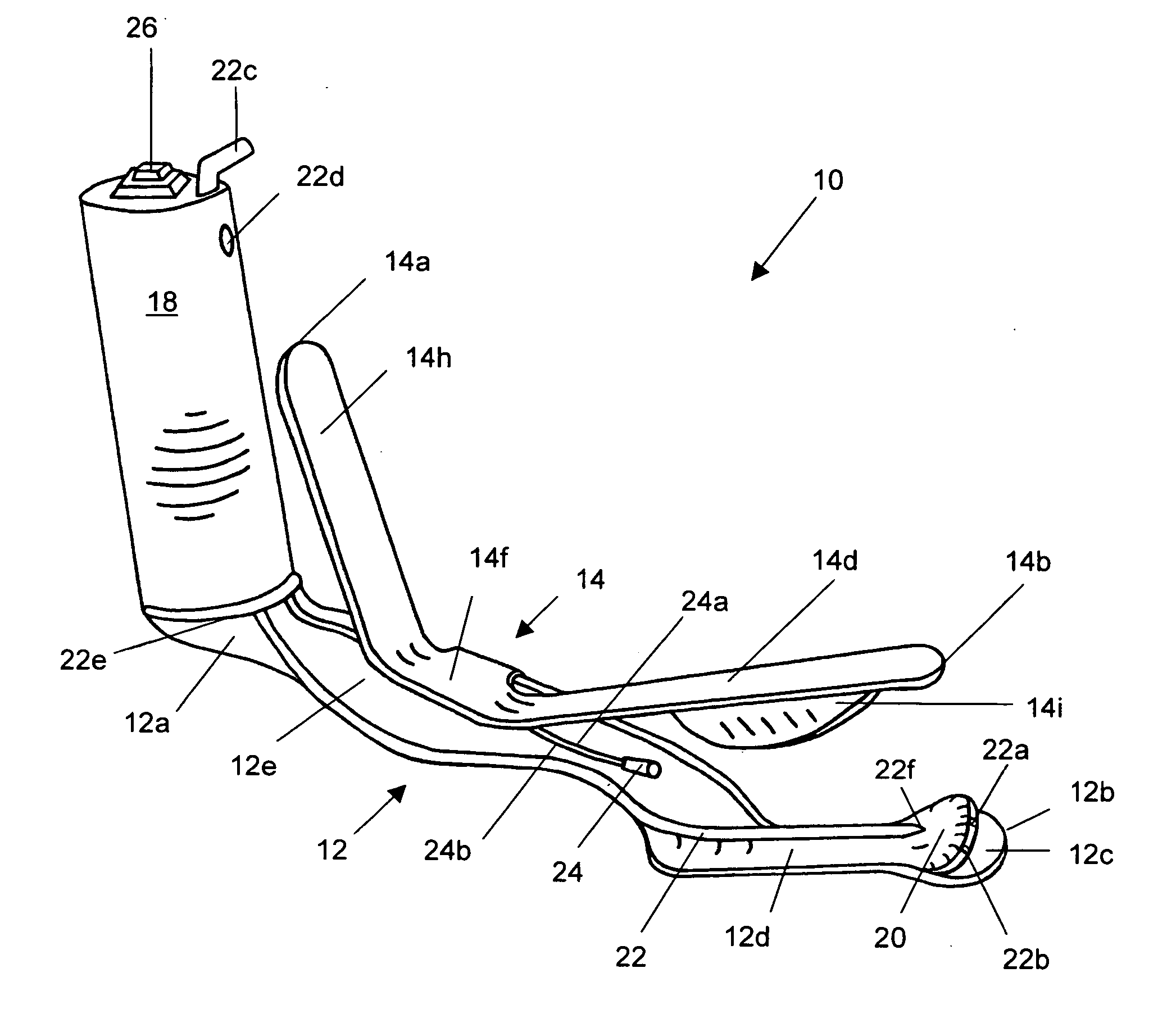
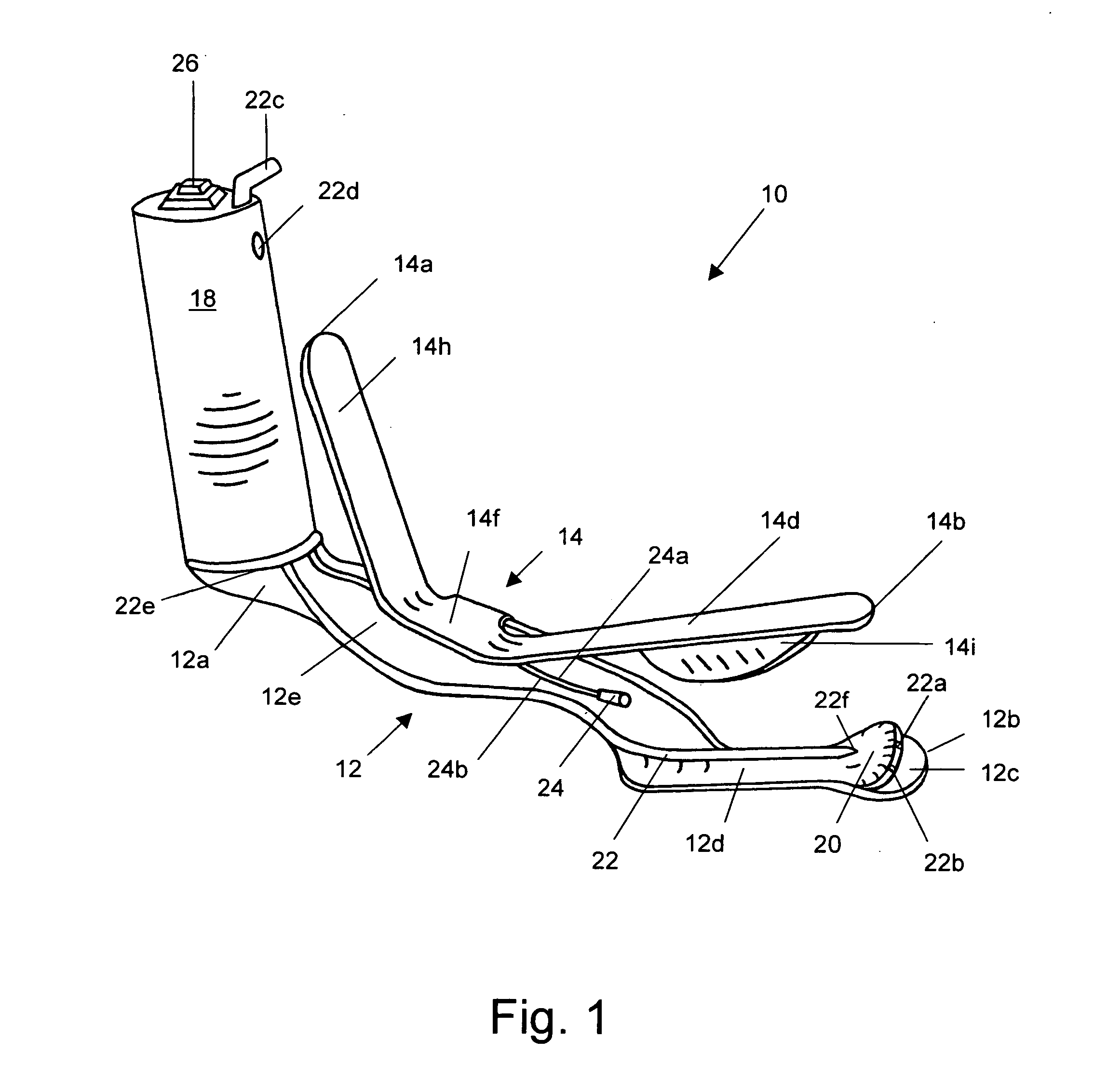
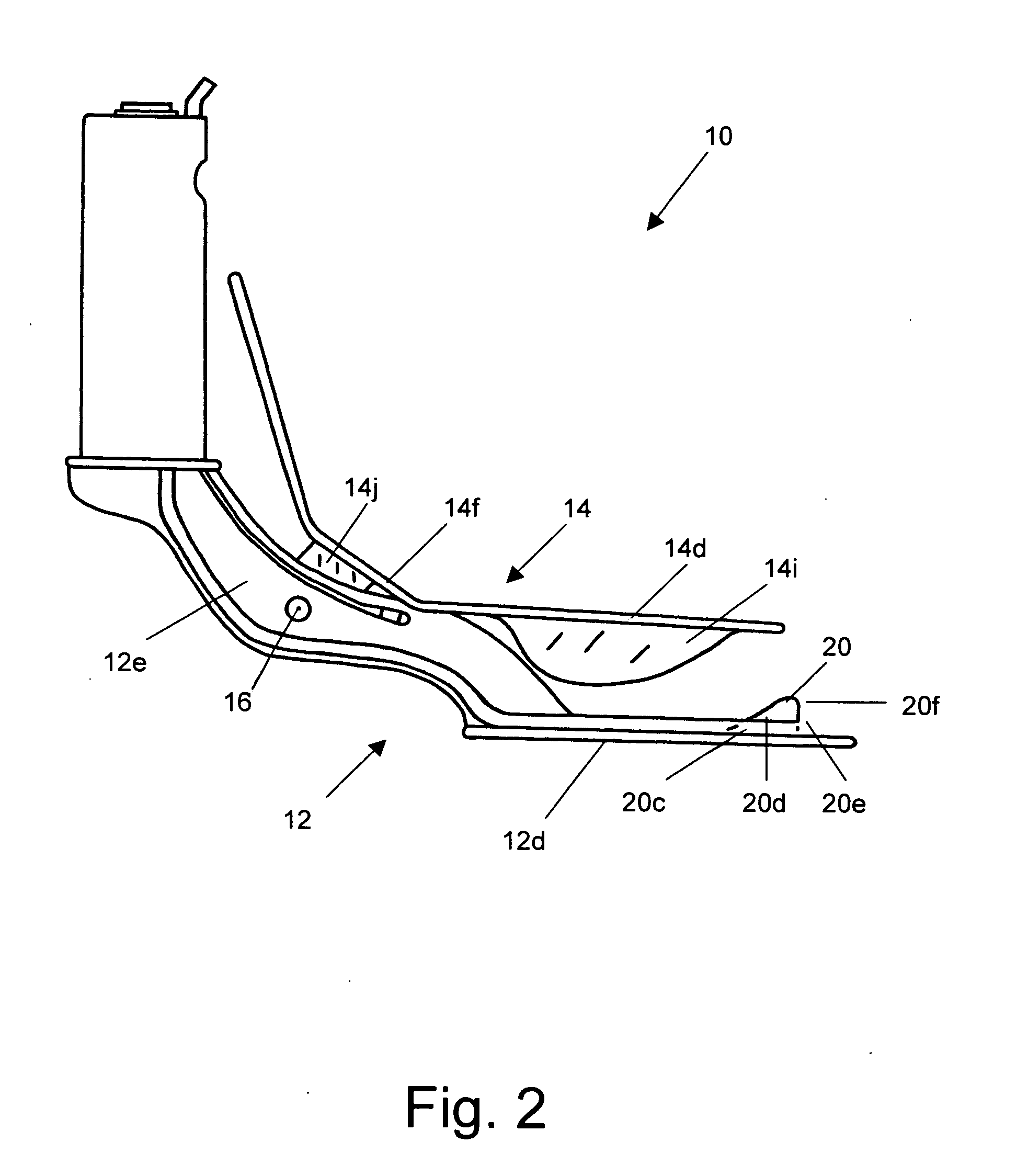
[0012] A laryngoscope is provided that has a lower blade and an upper blade pivotally connected to the lower blade, where the lower blade has a distal end adapted as an esophageal obturator for obstructing the esophagus. An arytenoid bumper is preferably secured to the lower blade near the distal end, and the arytenoid bumper may have a ramp or wedge shape and be adapted to direct an intubation tube through a patient's larynx into the trachea. A laryngoscope is also provided that has a lower blade and an upper blade pivotally connected to the lower blade, where the pivotal connection is on one side and the opposing side is open so that the laryngoscope may be removed after intubating a patient while leaving the intubation tube in place. The upper blade has a grip portion near the

Problems solved by technology

The intubation process is often difficult due to anatomic or pathologic differences between individuals.
The most common error in intubation is placing the tube in the esophagus instead of the trachea when the caregiver cannot adequately see the trachea or vocal cords.
Failure to recognize this error can lead to fatal hypoxia in an intubated patient, and some studies have shown a failure rate of up to 30% for intubations made in the field.
In an effort to minimize this failure rate, some laryngoscopes include fiber optics for visualizing the vocal cords for proper tube placement, however these devices are very expensive and are not widely available.
The EOA lacks proven effectiveness and is considered dangerous by design.
A complicated rack and pinion gear system is used to open the blades.
The primary disadvantage of this art is that the fiber optics and complicated design make it very expensive.
Another disadvantage is that you must disassemble the endotracheal tube by removing the proximal fitting that connects the tube to an oxygen source in order to remove the laryngoscope, and there is no mechanism for blocking the esophagus to ensure proper tube placement in the trachea.
In addition, the design of this laryngoscope makes it impossible to suction the patient without removing the entire laryngoscope first.
This wastes valuable seconds when trying to establish a patent airway for a patient.
However, other than illuminating the airwary, this device provides no other assistive mechanisms to increase the ease and accuracy of intubation.
This exchanging of tubes can waste valuable seconds when seconds really count.
This could add precious seconds to the time a patient is without oxygen during this exchange.
However, these devices do not include features to decrease the likelihood of missed intubation, they are difficult to remove after insertion of the endotracheal tube, and they lack the ability to easily suction the patient using the same hand as the one holding the laryngoscope.
While there are suction devices that are operated independently of a laryngoscope, there are none that are integral to the laryngoscope itself.
This process is awkward and unwieldy.

Method used


Image

  • Dual blade laryngoscope with esophageal obturator
  • Dual blade laryngoscope with esophageal obturator
  • Dual blade laryngoscope with esophageal obturator

Examples


Embodiment Construction

[0018] 1. Preferred Embodiment.

[0019] The present invention is directed to a dual-bladed laryngoscope adapted for blocking the opening to the esophagus and preventing a tube from entering the esophagus during intubation. The laryngoscope preferably includes a ramp for guiding the intubation tube into the trachea. Another aspect of the invention includes a hinge connection between the two blades, where one side of the two blades are pivotally connected with the other side open so that an intubation tube may remain in place while the laryngoscope is removed. The intubation tube passes through the open side of the laryngoscope. The laryngoscope may further include a tongue guard for holding the tongue out of the way when forming a passageway through which to guide an intubation tube, a light for illuminating the passageway thus formed, and an integrated suction tube operated by a finger of the hand holding the laryngoscope.

[0020] With reference to FIG. 1, one embodiment of a laryngos...


PUM


Abstract

A dual bladed laryngoscope for quickly and easily intubating a patient. The invention has two blades pivotally hinged on one side while the opposing side is open allowing the laryngoscope to be easily removed after intubating a patient. The proximal end of the upper blade has a grip portion which can be moved closer to or farther away from the handle attached to the proximal end of the lower blade to open or close the distal ends of the lower and upper blades. The lower blade of the invention has a distal end adapted as an esophageal obturator for obstructing the esophagus. An arytenoid bumper to prevent the laryngoscope from penetrating too far into the esophagus is preferably secured to the distal end of the lower blade. The arytenoid bumper may have a ramp or wedge shape adapted to deflect an intubation tube through a patient's larynx and into the trachea. The upper blade optionally has a tongue guard adapted to hold the tongue outside of a channel formed by the lower blade, the tongue guard and the upper blade. A suction conduit is optionally built in or secured to either the lower blade or the upper blade for providing a tube for suctioning secretions or emesis. A suction break is located in the handle of the laryngoscope to allow a finger of the hand holding the laryngoscope to control the presence and intensity of suction.

Description

CROSS REFERENCE TO RELATED APPLICATION [0001] Priority is claimed to U.S. Provisional Patent Application Ser. No. 60 / 500,107 filed by the inventor on Sep. 4, 2003, which is incorporated by reference.BACKGROUND OF THE INVENTION [0002] 1. Field of the Invention [0003] The present invention relates to a medical device for intubating a patient, and more particularly to a dual-bladed laryngoscope. [0004] 2. Description of the Related Art [0005] It is often necessary to put a tube in a person's airway for assisting in breathing, such as emergency situations where a patient or victim is no longer able to breath normally, or during anesthesia or cardiac arrest to prevent aspiration of mucus, vomit, or particulate matter into the lungs. This procedure is referred to as endotracheal intubation. A laryngoscope may be used to assist a caregiver in performing this procedure. Laryngoscopes may be comprised of a single blade, which may be straight or curved for guiding the tube into the trachea, o...

Claims


Application Information

Patent Timeline
IPC IPC(8): A61B1/12A61B1/267
CPCA61B1/00094A61B1/12A61B1/267
Inventor CANTRELL, ELROY
Owner SCOPECO
Learn More