Device for determining interference region of robot

a robot and interference technology, applied in the field of robot interference detection devices, can solve the problems of operator hitch in work, safety fences and the like in the workplace, waste of time and energy to relocate, etc., and achieve the effect of convenient procedure and easy determination

Inactive Publication Date: 2005-03-10
FANUC LTD
View PDF24 Cites 56 Cited by
  • Summary
  • Abstract
  • Description
  • Claims
  • Application Information

AI Technical Summary

Benefits of technology

Inventors have developed devices called robots or manipulators used during manufacturing processes. These machines can be equipped with sensory systems like cameras to capture images about their surroundings while they work together inside them. By analyzing these captured data, operators are able to see how well everything works alongside each other without being distracted too much. They then use those results to make informed decisions regarding placement of objects within specific areas around them. Overall, these technical improvements improve efficiency and accuracy in industrial production process automation.

Problems solved by technology

The technical problem addressed in this patent text is the difficulty in determining the proper location of peripheral objects, such as a jig and safety fence, in a workplace where a robot operates. This can lead to interference accidents and waste of time and energy relocating them. The prior art methods of pre-arranging peripheral objects and simulating robot operation are not always effective in preventing interference, and there is no way to recognize interference between the robot arm and the peripheral objects after installation.

Method used


Image

  • Device for determining interference region of robot
  • Device for determining interference region of robot
  • Device for determining interference region of robot

Examples


Embodiment Construction

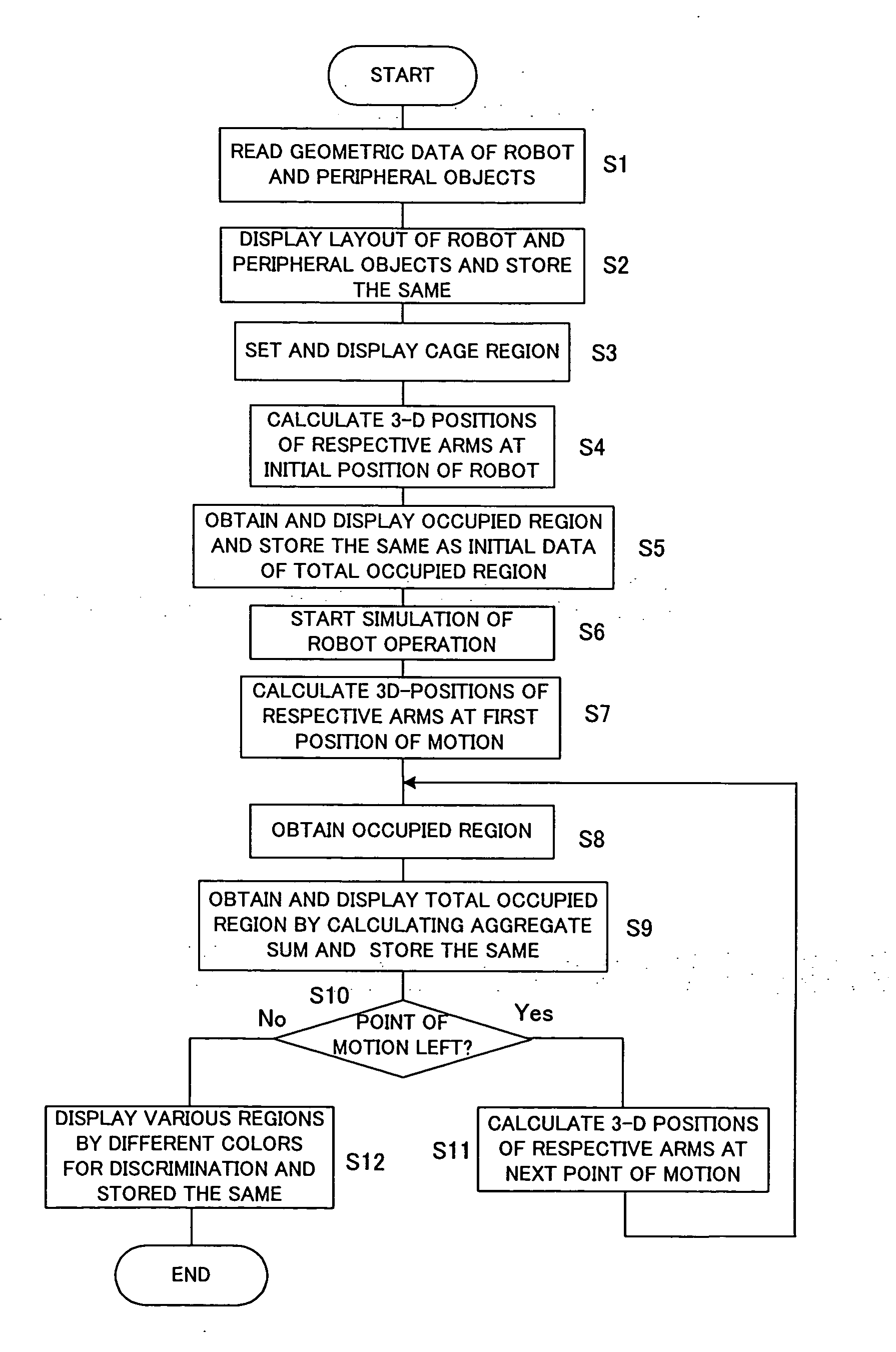
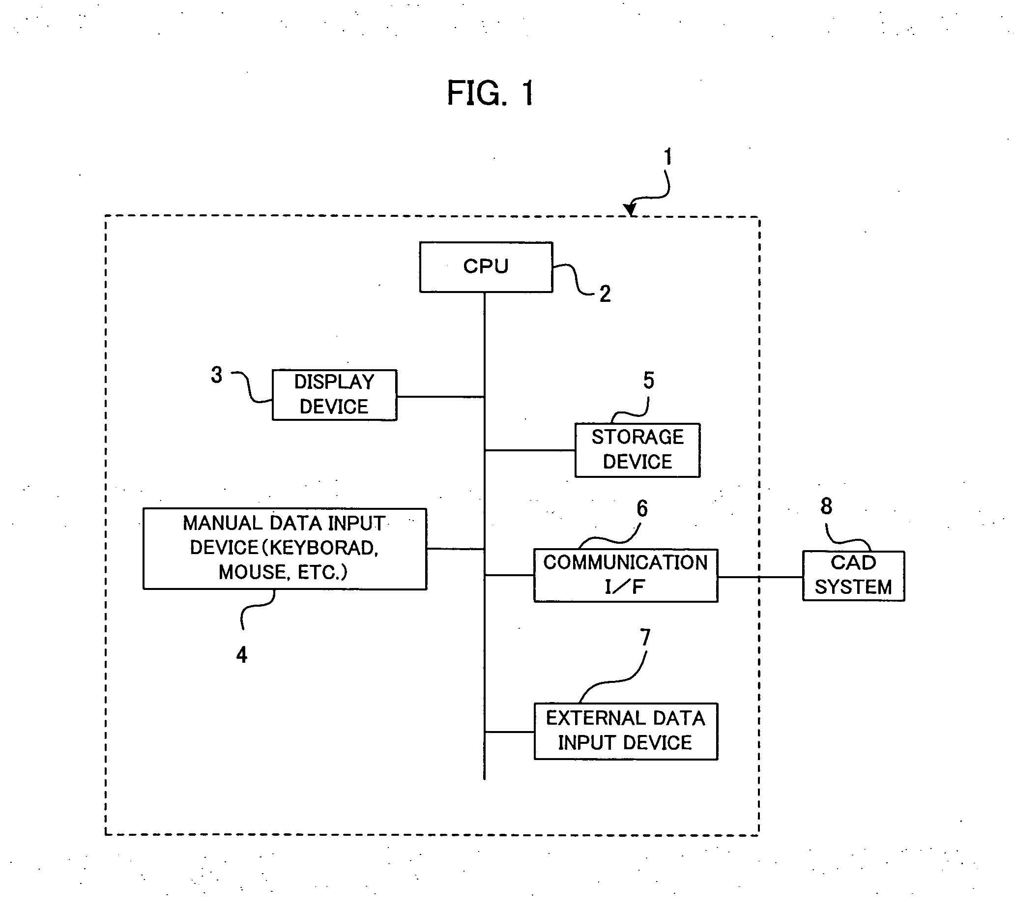
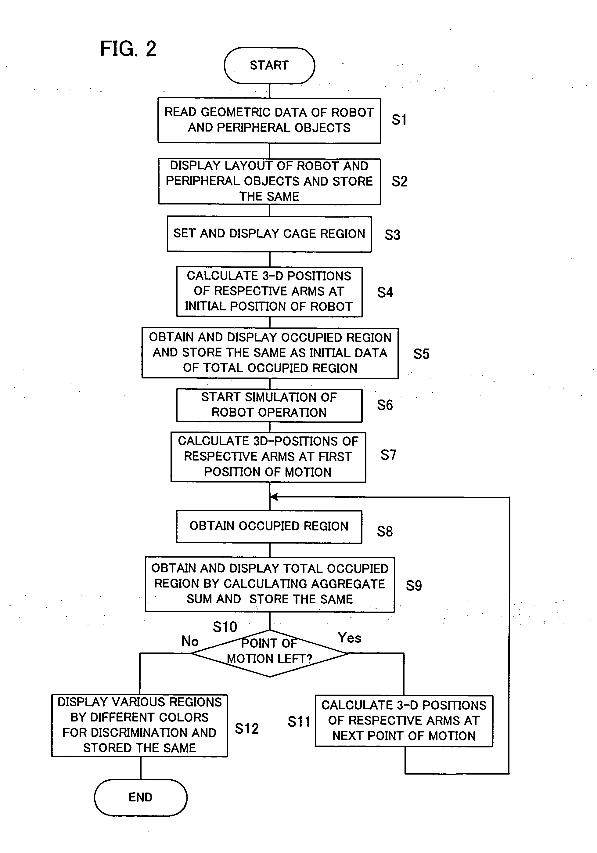
[0024]FIG. 1 is a block diagram showing a system configuration including a device for determining an interference region of a robot according to the present embodiment. In FIG. 1, a device 1 for determing an interference region of a robot comprises a CPU 2, a display device 3 connected to a bus line of the CPU 2, a manual data input device 4, a storage device 5, a communication interface 6 and an external data input device 7. A reference character 8 represents a CAD system connected to the device 1 for determining an interference region of a robot through the communication interface 6. It is possible to read three-dimensional geometric data (including dimensional data) of the robot which is a simulation target, three-dimensional geometric data (including dimensional data) in a state where the robot is equipped with an end effector (such as tool), three-dimensional geometric data (including dimensional data) of peripheral objects (such a jig and a safety fence), and the like, from th...


PUM


Abstract

A device for determining an interference region of a robot, capable of determining an interference region/non-interference region and the like on an off-line layout space without difficulty. Geometric data of a robot and peripheral objects is read from a CAD system or the like to be displayed in the form of a layout display, to thereby form a cage region. An initial occupied region is found by calculating a three-dimensional position of each arm at an initial position. An operation simulation is run, and the tree-dimensional positions are repeatedly calculated, thereby finding the aggregate sum of the occupied region. After the robot is moved, a total occupied region G, an overlapping region H, a protruding region K, a non-occupied region M and the like are displayed in different colors, to thereby perform layout correction of a peripheral object, a change of the cage region, etc. It is also possible to judge the presence or absence of the overlapping region H/protruding region K and to search “a hidden non-occupied region” by way of a sectional display in which points A, B and C are designated.

Description


Claims


Application Information

Patent Timeline
Owner FANUC LTD
Why Eureka
Try Eureka