Wheel grip factor estimating apparatus and vehicle motion control apparatus

a technology for estimating apparatus and wheel grip, which is applied in the direction of process and machine control, braking systems, instruments, etc., can solve the problems of inability to control the dead zone, the vehicle shows a tendency to swelling on the outside of the curve, and the vehicle velocity cannot be reduced by the control

Inactive Publication Date: 2005-03-10
ADVICS CO LTD +1
View PDF5 Cites 39 Cited by
  • Summary
  • Abstract
  • Description
  • Claims
  • Application Information

AI Technical Summary

Benefits of technology

Therefore, one of objects of the invention is to provide a grip factor estimating apparatus which can accurately estimate the grip factor indicating the grip level of lateral grip of each wheel so that a driver can be alarmed when, for example, the grip factor is lower than a first predetermined value.
Another object of the invention is to provide a grip factor estimating apparatus which can estimate the grip factor accurately without any influence of braking or driving force applied on each wheel though self-aligning torque is affected by the braking or driving force.
A further object of the invention is to provide a vehicle motion control apparatus which can estimate the grip factor accurately without influence of the braking or driving force and which can control the motion of the vehicle appropriately on the basis of the grip factor when the grip factor is lower than a second predetermined value.

Problems solved by technology

Moreover, in the actual control system, there is a dead zone incapable of being controlled.
Accordingly, when the velocity of approach to the curve is high, side force generated in the wheels does not balance with centrifugal force so that the vehicle shows a tendency to swelling on the outside of the curve.
However, as the control starts at the cornering limit, there is a possibility that the vehicle velocity cannot be reduced sufficiently by the control.
There is a possibility that swelling on the outside of the curve cannot be prevented by only the aforementioned control.

Method used


Image

  • Wheel grip factor estimating apparatus and vehicle motion control apparatus
  • Wheel grip factor estimating apparatus and vehicle motion control apparatus
  • Wheel grip factor estimating apparatus and vehicle motion control apparatus

Examples


Embodiment Construction

Referring now to the accompanying drawings, a description will be given in detail of preferred embodiments of the invention.

1. Embodiment of Grip Factor Estimating Apparatus

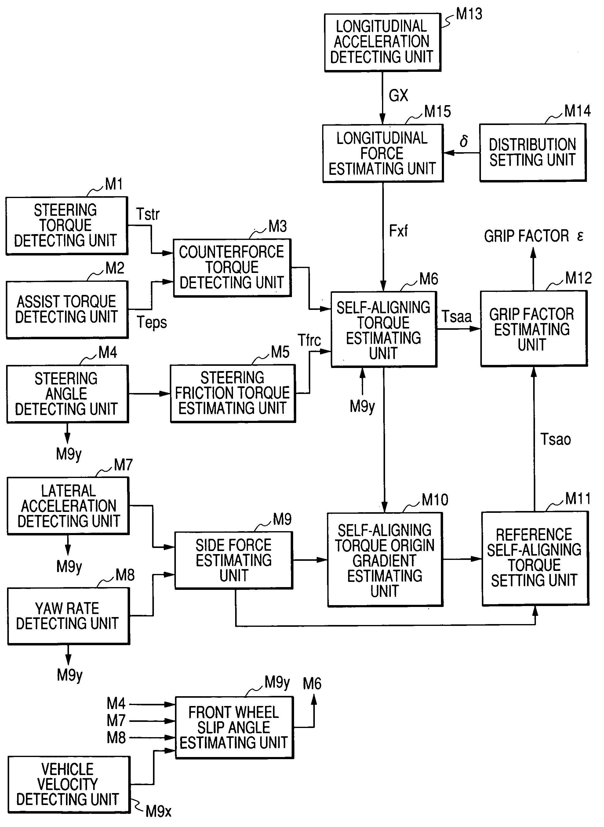
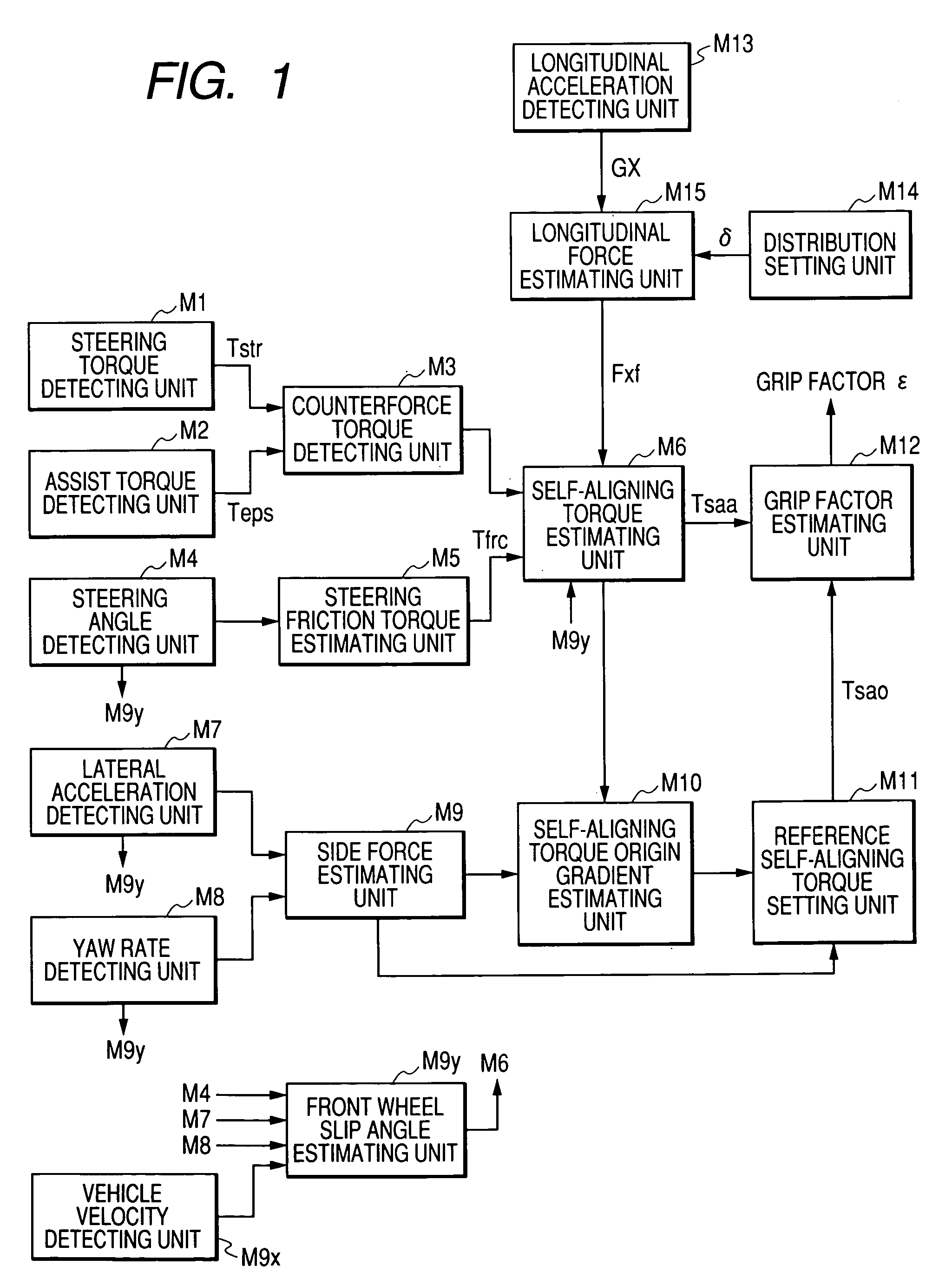
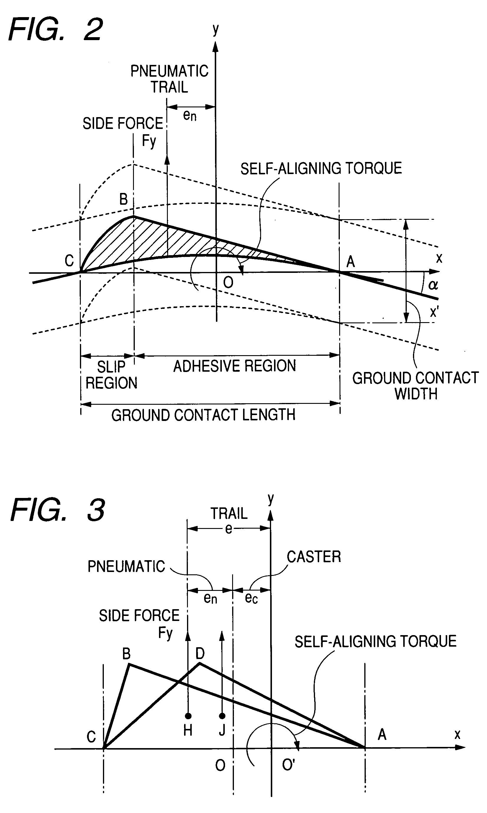
FIG. 1 is a block diagram showing a main configuration of a grip factor estimating apparatus for estimating the degree of grip on the basis of side force and self-aligning torque according to an embodiment of the invention. First, an example of estimation of the grip factor will be described with reference to FIGS. 2-4.

As is obvious from FIGS. 2 and 3, characteristic of self-aligning torque relative to front wheel side force applied on wheels in the front of a vehicle (hereinafter referred to as front wheels) is given as represented by Tsa in FIG. 4. As described above, actual self-aligning torque Tsaa is given by the expression Tsaa=Fyf·(en+ec) in which Fyf is front wheel side force. Accordingly, nonlinear characteristic of the actual self-aligning torque Tsaa with respect to the front wheel side force Fyf...


PUM


Abstract

A grip factor estimating apparatus includes a steering torque detecting unit M1, and an assist torque detecting unit M2. When a self-aligning torque estimating unit M6 estimates self-aligning torque generated in front wheels on the basis of detection result of the detecting unit, the quantity of influence of longitudinal force on self-aligning torque is removed on the basis of longitudinal force acting on the front wheels and estimated by a longitudinal force estimating unit M15 and a front wheel slip angle estimated by a front wheel slip angle estimating unit M9y. A grip factor estimating unit M12 estimates the grip factor of the front wheels on the basis of change in self-aligning torque in accordance with the side force.

Description

CROSS-REFERENCE TO THE RELATED APPLICATION(S) This application is based upon and claims a priority from a prior Japanese Patent Application No. 2003-314517 filed on Sep. 5, 2003, the entire contents of which are incorporated herein by reference. BACKGROUND OF THE INVENTION 1. Field of the Invention The present invention relates to an apparatus for estimating the grip factor of wheels and particularly to an apparatus for estimating the grip factor indicating the grip level of wheels in the front of a vehicle in a lateral direction. The invention also relates to a vehicle motion control apparatus equipped with the grip factor estimating apparatus. 2. Description of the Related Art There is known an apparatus for detecting and judging the state variable of a vehicle and controlling braking force of wheels independently to retain the stability of the vehicle. For example, this type apparatus has been disclosed in JP-A-6-099800. According to the document JP-A-6-099800, a target valu...

Claims


Application Information

Patent Timeline
Patent Type & Authority Applications(United States)
IPC IPC(8): B60R16/02B60T8/172B60T8/1755B60T8/1763B60W40/068B60W40/101B60W40/103B62D6/00
CPCB60T8/172B60T8/17551B60T2210/12B62D6/006B60T2260/02B60W40/068B60W2510/202B60T2230/02
Inventor KATO, HIROAKIMOMIYAMA, MINEKAZUYASUI, YOSHIYUKIMURAGISHI, YUJIIMOTO, YUZOAIZAWA, HIROAKI
Owner ADVICS CO LTD
Why Eureka
Try Eureka