Skylight having a molded plastic frame

a technology of skylights and frames, applied in skylights/domes, building roofs, doors/windows, etc., can solve the problems and affecting the appearance of the skylight. , to achieve the effect of reducing the weight of the skylight frame-curb assembly

Active Publication Date: 2005-03-17
V TECH PATENTS
View PDF9 Cites 37 Cited by
  • Summary
  • Abstract
  • Description
  • Claims
  • Application Information

AI Technical Summary

Benefits of technology

[0012] In another embodiment of the present invention, a skylight frame-curb assembly having a U-shaped trough with a mounting flange extending from one side of the U-shaped trough is provided. The skylight frame-curb assembly of this embodiment also includes the stepped frame section as described above. The trough of the present embodiment is filled with a foamed plastic in order to provide rigidity while reducing the weight of the skylight frame-curb assembly.

Problems solved by technology

However, since the installation of a skylight requires that an opening be cut in a roof, sealing such units has presented numerous challenges.
Over time this leak tight seal often degrades and leaks.
Furthermore, the application of a sealant to the curb may cause complications with the skylight manufacture tolerances by leaving a space between the metal flashing along the sides of the curb and the top of the curb.
However, such tapes do not adhere as well as sealants.
Such configurations tend to be expensive and require rather strict tolerances.
Moreover, the gasket can not be modified on-site.
However, the RIM process presents a number of considerations that complicates part fabrication.
Finally, the relatively protracted cycle times for forming larger parts and the limited choices of polymers (mostly polyurethanes) make RIM a somewhat undesirable process.

Method used


Image

  • Skylight having a molded plastic frame
  • Skylight having a molded plastic frame
  • Skylight having a molded plastic frame

Examples


Embodiment Construction

[0036] Reference will now be made in detail to presently preferred compositions or embodiments and methods of the invention, which constitute the best modes of practicing the invention presently known to the inventors.

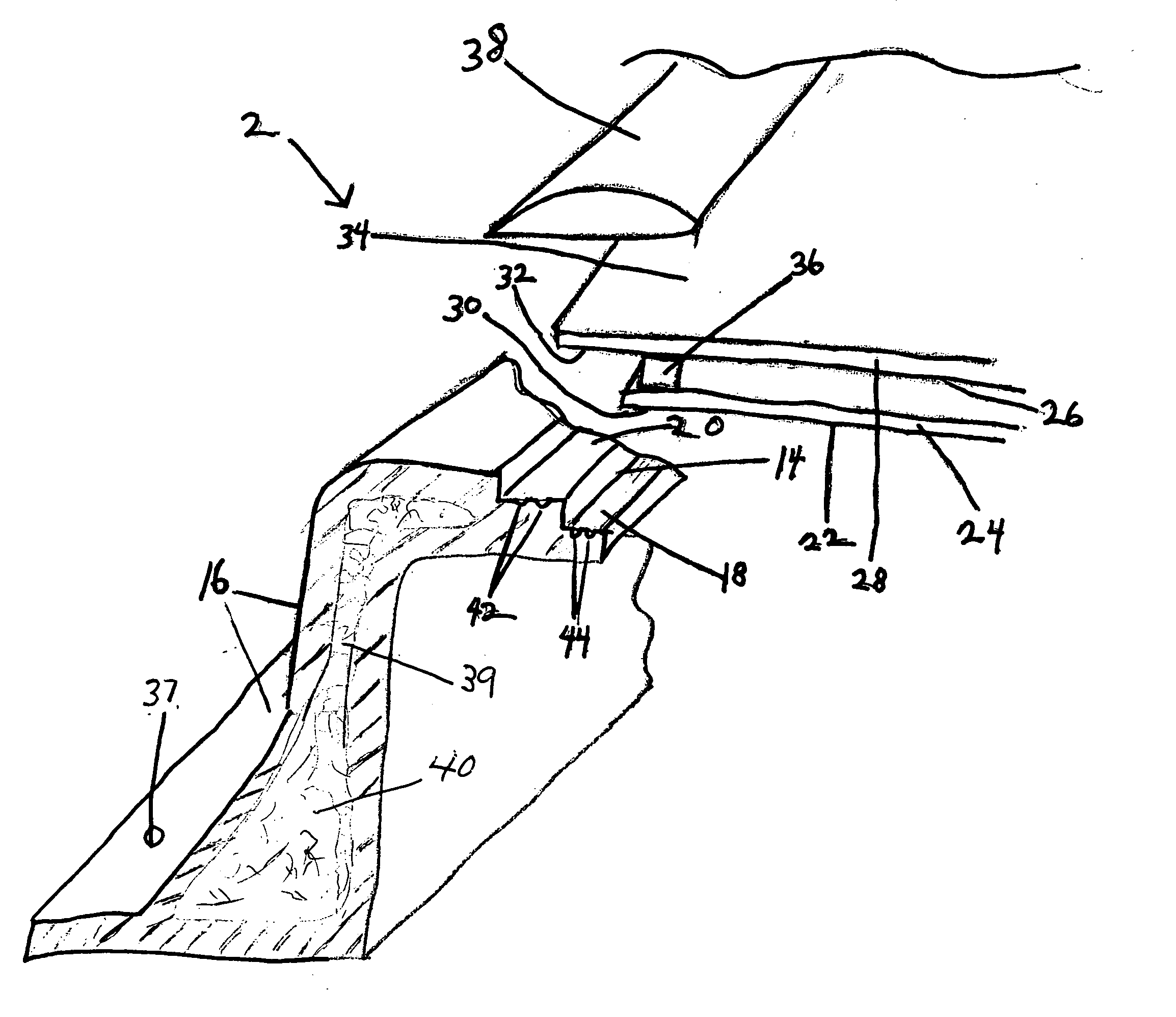
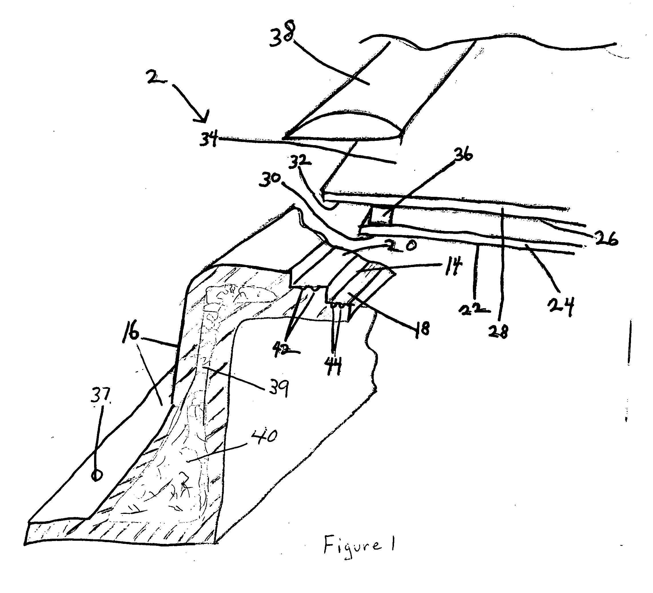
[0037] In an embodiment of the present invention, a skylight frame-curb assembly adapted to receive at least two panels of glass is provided. The skylight frame-curb assembly of the present invention comprises a quadrilateral frame with an integral stepped frame section. The quadrilateral frame is preferably substantially rectangular. The stepped frame surface includes a lower step surface and an upper step surface. The lower step surface is adapted to receive a first glass panel so that a section of the first glass panel lies flush against the lower step surface. Similarly, the upper step surface is adapted to receive a second glass panel so that the second glass panel lies flush against the upper step surface.

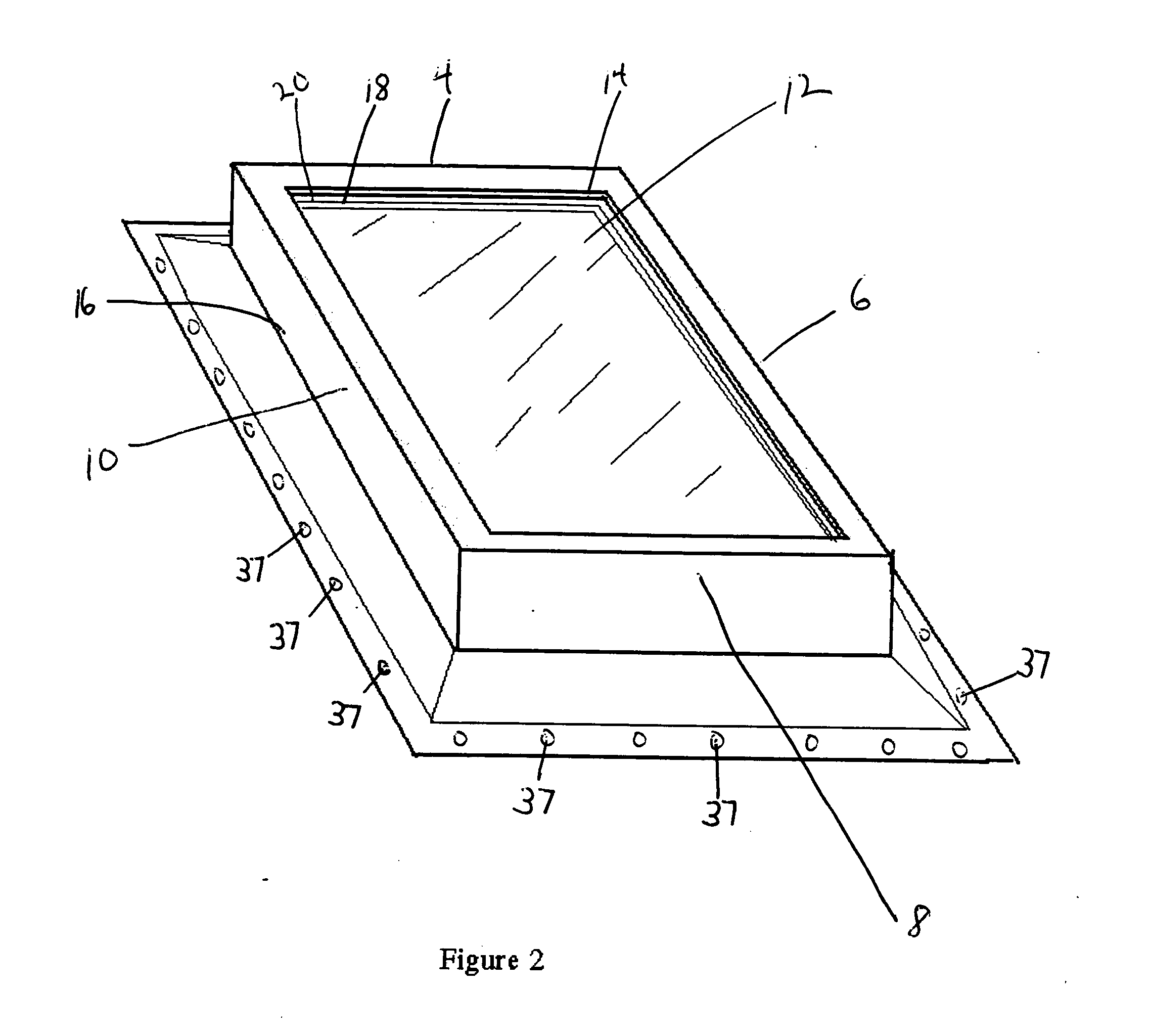
[0038] With reference to FIGS. 1 and 2, a perspective vi...


PUM


Abstract

The present invention provides a skylight frame design that is adapted to receive at least two panels of glass. The skylight frame comprises a stepped frame section that includes a lower step surface and an upper step surface. The lower step surface is adapted to receive a first glass panel so that a section of the first glass panel lies flush against the lower step surface. Similarly, the upper step surface is adapted to receive a second glass panel so that the second glass panel lies flush against the upper step surface. The skylight frame design of the invention is either incorporated into a skylight frame that may be attached to a curb unit on a roof or it may be an integral part of a skylight frame-curb assembly that also contains a curb section. In another embodiment of the invention, a skylight frame design which directly incorporates one or more panels of glass during molding is provided.

Description

BACKGROUND OF THE INVENTION [0001] 1. Field of the Invention [0002] The present invention relates to a skylight having a plastic frame. [0003] 2. Background Art [0004] Skylights have been used to allow light into residential and commercial buildings through an opening. The aesthetic value and possible health benefits of having sunlight in buildings have lead to an increasing demand for these structures. Ideally, a skylight will let light in while keeping other environmental elements out. However, since the installation of a skylight requires that an opening be cut in a roof, sealing such units has presented numerous challenges. [0005] Popular skylight configurations include, for example, fixed skylights with flat or domed-shaped glass, ventilation skylights, egress skylights, and balcony skylights. In the fixed skylight configuration, the skylight functions essentially as a window that does not open. Ventilation skylights are similar, but may be opened a few inches to allow air circ...

Claims


Application Information

Patent Timeline
Patent Type & Authority Applications(United States)
IPC IPC(8): E04B7/00E04B7/18E04DE04D13/03
CPCE04D13/0305E04D13/0315E06B3/6617
Inventor VALENTZ, ARTHUR J.NEMAZI, JOHN E.PROSCIA, JAMES W.
Owner V TECH PATENTS
Why Eureka
Try Eureka