Gas sampling bag

a sampling bag and gas technology, applied in the field of gas sampling bags, can solve the problems of limited overall capacity of the bag main body b>52/b>, and cannot be increased in relation to the duration of the test mode and the injection flow ra

Active Publication Date: 2005-03-17
HORIBA LTD
View PDF4 Cites 11 Cited by
  • Summary
  • Abstract
  • Description
  • Claims
  • Application Information

AI Technical Summary

Benefits of technology

[0014] At the more detailed level, it is further comprehended that in the gas sampling bag having such a configuration, since the size of the opening of the plurality of gas inlet / outlet holes formed in the pipe contained in the bag main body is determined so that the pressure loss may be suppressed to be minimum so as not to increase as far as possible, the pressure in all the gas inlet / outlet holes is generally higher than in the conventional gas sampling bag; hence, the flow rate of the gas blown out from the gas inlet / outlet holes into the bag main body is higher. As a result, not limited to the plural gas inlet / outlet holes in the vicinity of the gas junction, the gas is blown out almost uniformly from all gas inlet / outlet holes opened in the pipe, and flows into the bag main body.

Problems solved by technology

However, in the gas sampling bag 51 connected to the constant volume sampling passage, the overall capacity of the bag main body 52 is limited, and cannot be increased simply in relation to the test mode duration and injection flow rate.

Method used


Image

  • Gas sampling bag
  • Gas sampling bag
  • Gas sampling bag

Examples


Embodiment Construction

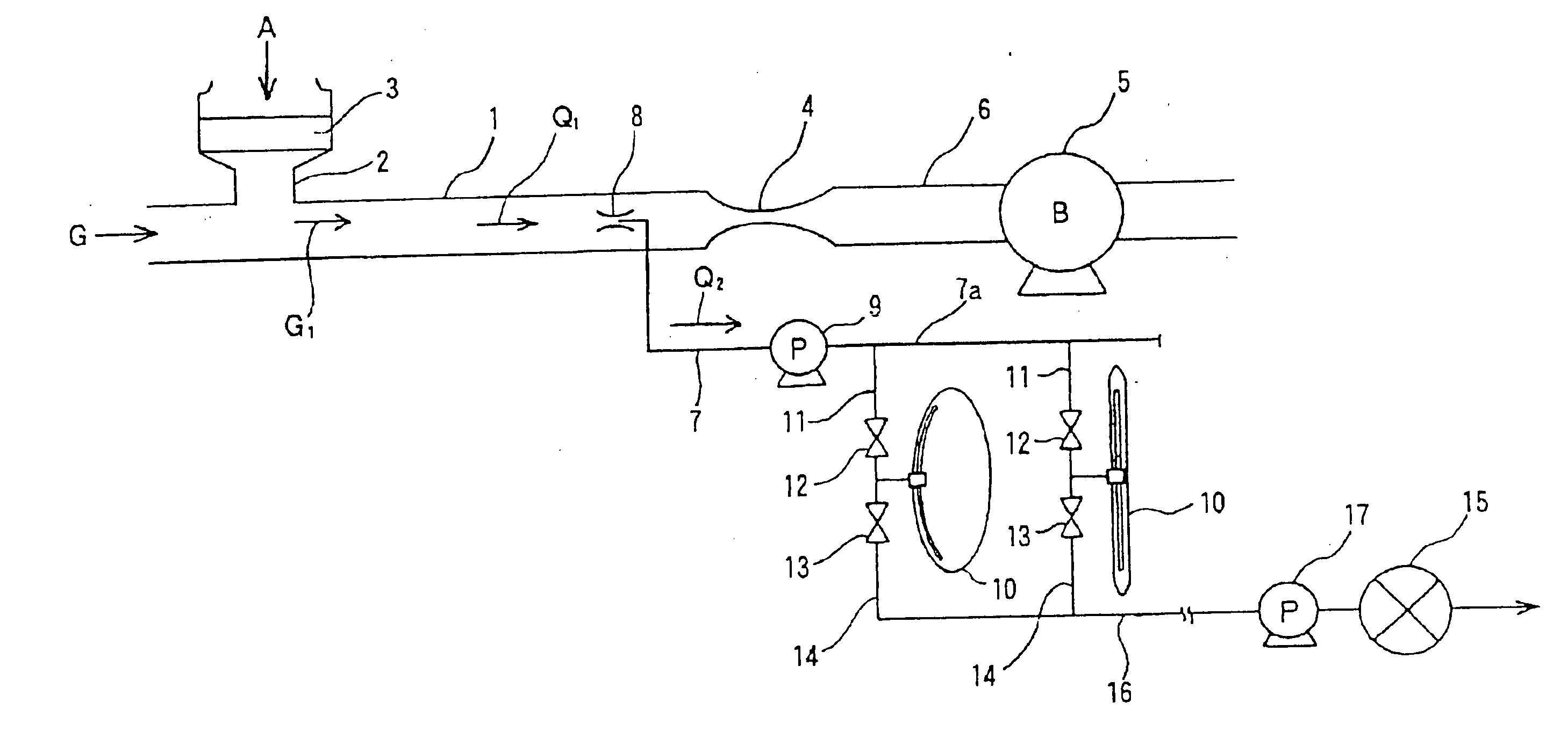
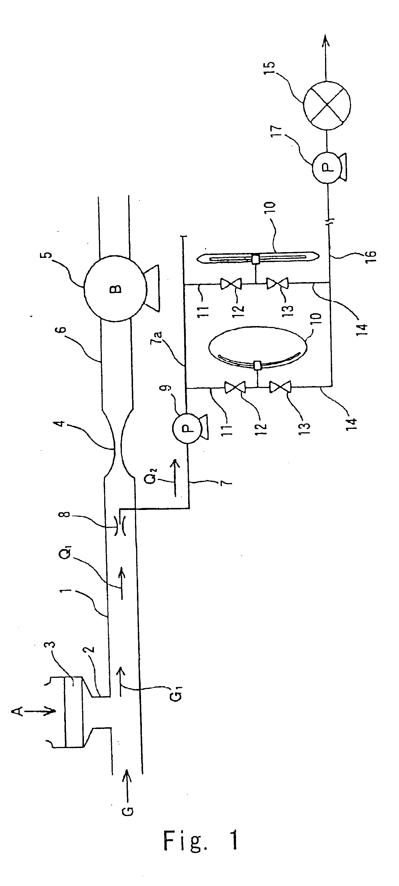
[0021] FIGS. 1 to 4 show a preferred embodiment of the invention. FIG. 1 is a diagram schematically showing an example of an automobile emission measuring apparatus in which a gas sampling bag of the invention is assembled. In FIG. 1, reference numeral 1 denotes a sample gas diluting pipe, and emission gas G exhausted from an automobile engine as an emission source flows in from its upstream side. Reference numeral 2 denotes a diluting air introduction pipe connected to the sample gas diluting pipe 1, and diluting air A is introduced into the sample gas diluting pipe 1 through a filter 3. Reference numeral 4 denotes a venturi tube connected to the downstream side of the sample gas diluting pipe 1, and reference numeral 5 denotes a blower as a suction device provided in a duct 6 at the downstream side of this venturi tube 4, and emission gas diluted by the air A (hereinafter, referred to as “diluted emission gas”) G1 is sucked in at a specified flow rate Q1 by the blower 5.

[0022] Re...


PUM

PropertyMeasurementUnit
diameteraaaaaaaaaa
diameteraaaaaaaaaa
sizesaaaaaaaaaa

Abstract

A gas sampling bag is capable of blowing out the gas uniformly into the bag main body, and filling the bag main body with gas in a securely mixed state. A gas sampling bag that is connected to a constant volume sampling passage, contains a pipe, on which a plurality of gas inlet/outlet holes are formed, in a bag main body, and allows the gas to flow into/out of the bag main body through the gas inlet/outlet holes. The opening of the plurality of gas inlet/outlet holes is formed in such a manner that the size is minimized while the pressure loss is suppressed so as not to increase as far as possible.

Description

BACKGROUND OF THE INVENTION [0001] 1. Field of the Invention [0002] The present invention relates to a gas sampling bag and, more particularly, to a gas sampling bag that is connected to a constant volume sampling passage, contains a pipe, on which a plurality of gas inlet / outlet holes are formed, in a bag main body, and allows gas to flow into / out of the bag main body through the gas inlet / outlet holes. [0003] 2. Background Art [0004] One of the sampling methods of emission gas exhausted from an automobile engine or the like is, for example, the constant volume sampling (CVS) method. In this CVS method, the emission gas having transiently changing flow rate is diluted with the air, and the flow rate of the diluted gas is defined as known flow rate, and the weight of components is calculated by using the diluted gas component concentration and the known flow rate. [0005] In one of the measuring techniques of gas concentration of the CVS method, the sampled diluted gas is put in a ga...

Claims


Application Information

Patent Timeline
Patent Type & Authority Applications(United States)
IPC IPC(8): G01N1/22
CPCG01N2001/2264G01N1/2252
Inventor HIRAI, HITOSHIOHASHI, HIDEKIMIZUTAKA, TOSHIOYODA, KIMIKAZUUCHIDA, KENICHIKATUMATA, HIROAKI
Owner HORIBA LTD
Why Eureka
Try Eureka