

Ceramic structure and process for producing the same
a ceramic structure and process technology, applied in chemical/physical processes, metal/metal-oxide/metal-hydroxide catalysts, machines/engines, etc., can solve the problems of increasing pressure loss, reducing the purification efficiency of ceramic catalyst bodies, and increasing pressure loss in inverse proportions, so as to prevent the damage of the ceramic catalyst body from being damaged by thermal stress and thermal stress in a case.
Active Publication Date: 2012-10-09
NGK INSULATORS LTD
View PDF25 Cites 14 Cited by
- Summary
- Abstract
- Description
- Claims
- Application Information
AI Technical Summary
Benefits of technology
The present invention provides a ceramic structure that can be used as a ceramic catalyst body with excellent purification efficiency, reduced pressure loss, and mountable in limited space. The ceramic structure has a controlled pore distribution with a high percentage of pores having pore diameters smaller than 20 μm and a low percentage of pores having pore diameters larger than 20 μm. The ceramic structure has a honeycomb structure with a plurality of cells communicating between two end faces, and a thermal expansion coefficient of 1.0×10⁻⁶ / °C or less. The ceramic structure can be produced using a ceramic material containing a cordierite forming material containing alumina, magnesia, and silica. The ceramic structure can be formed by blending the ceramic material with a pore former such as graphite, foam resin, water absorbing polymer, or flour. The process for producing the ceramic structure can be employed for obtaining a ceramic structure with a porosity of 50 to 70% and a thermal expansion coefficient of 1.0×10⁻⁶ or less at (40 to 800°C.
Problems solved by technology
However, pressure loss tends to increase in inverse proportion to the square of the hydraulic diameter of the cells, so that a problem occurs that the pressure loss also increases with the improvement of the transmission ratio of the components to be purified.
Moreover, it is known that in a case where the rate of diffusion of the components to be purified in the catalyst layer, the purification efficiency of the ceramic catalyst body tends to decrease.
However, in this case, the cell density and the surface area of the catalyst layer are easily increased, and the transmission ratio of the components to be purified increases, but the problem that the pressure loss increases is not solved.
However, when the size of the ceramic catalyst body is enlarged, a mounting space is limited, so that a problem that it becomes difficult to mount the structure on a car remains to be unsolved.Patent Document 1: JP-A 2003-33664Patent Document 2: JP-A 2002-219319Patent Document 3: JP-A 2002-301323
Method used
View moreImage
Smart ImageViewing Examples

Examples
examples
[0051]Examples of the present invention will hereinafter specifically be described, but the present invention is not limited to these examples.
Login to View More PUM
| Property | Measurement | Unit |
|---|---|---|
| pore diameter | aaaaa | aaaaa |
| pore diameter | aaaaa | aaaaa |
| pore diameter | aaaaa | aaaaa |
Abstract
There is disclosed a ceramic structure which comprises a material having a controlled pore distribution and including cordierite as the main crystal phase. In the pore distribution, the volume of pores having pore diameters smaller than 20 μm accounts for 15% or less of the total pore volume, and the volume of pores having pore diameters of 20 to 100 μm accounts for 70% or more of the total pore volume. This ceramic structure is suitable for realizing a ceramic catalyst body which has excellent purification efficiency, is reduced in pressure loss, and is mountable even in a limited space.
Description
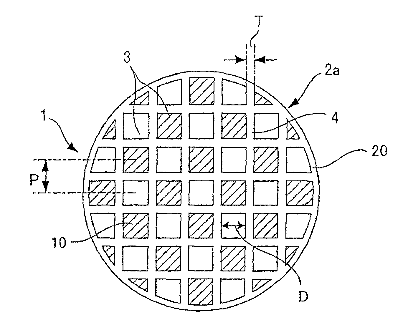
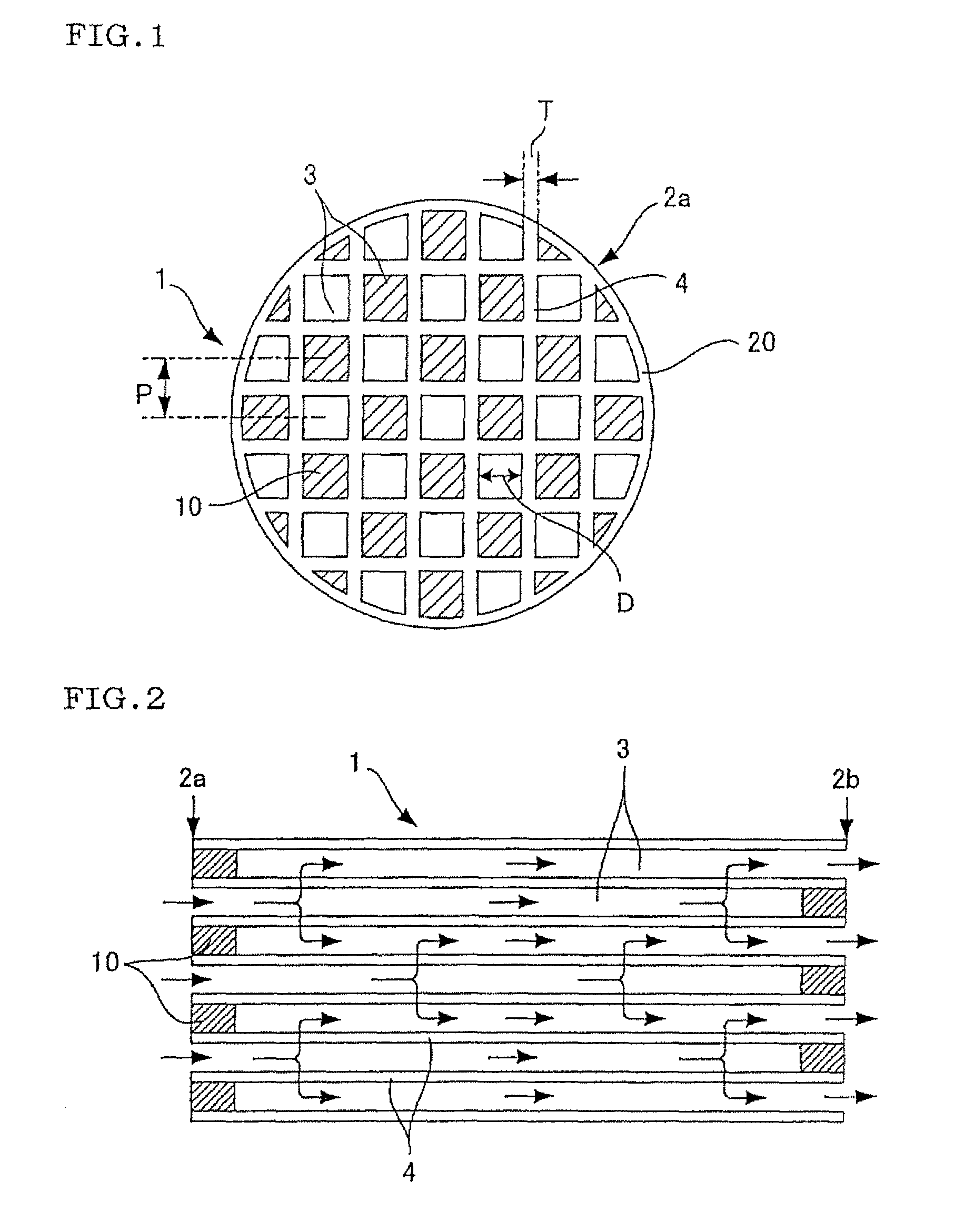
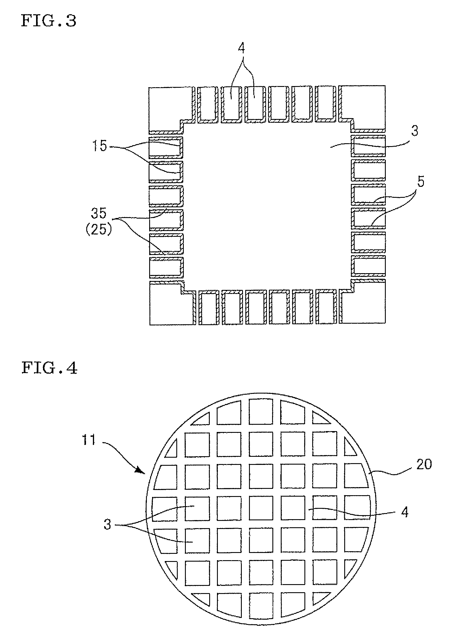
TECHNICAL FIELD[0001]The present invention relates to a ceramic structure on which a catalyst is carried and thereby which can become a ceramic catalyst body for use in purification of a component to be purified, for example, carbon monoxide (CO) included in an exhaust gas discharged from a car engine or the like, and it also relates to a process for producing the same.BACKGROUND ART[0002]To purify an exhaust gas discharged from any type of engine or the like, a catalyst body (hereinafter referred to as a ceramic catalyst body in the present description) is utilized in which a catalyst is carried on, for example, a ceramic structure (a honeycomb structure) having a honeycomb structure. FIGS. 4 to 6 are diagrams showing one example of the ceramic catalyst body. The ceramic catalyst body having the honeycomb structure has a structure in which a catalyst layer 15 is carried on the surface of a partition wall 4 forming a cell 3 as shown in FIG. 6. As shown in FIGS. 4, 5, the exhaust gas...
Claims
Login to View More Application Information
Patent Timeline
 Patent Type & AuthorityPatents(United States)
IPC IPC(8): C04B35/00C04B35/01C04B35/16C04B35/195C04B35/18
CPCB01D46/2429B01D46/247B01D46/2474B01J35/04C04B35/195C04B38/0006F01N3/0222C04B38/0054C04B38/0064Y10T428/24149B01D46/2466B01D2046/2433B01D2046/2437B01D2046/2496B01D2275/30C04B2111/00793C04B2111/0081C04B2235/3217C04B2235/3222C04B2235/3232C04B2235/3234C04B2235/3244C04B2235/3418C04B2235/3427C04B2235/3445C04B2235/3463C04B2235/3481C04B2235/349C04B2235/3826C04B2235/5436C04B2235/5472C04B2235/80C04B2235/9607F01N2330/06F01N2330/30B01D46/2444Y02T10/20Y02T10/12B01D46/2498B01D46/24492B01D46/2484B01D46/2482B01D46/24494B01J35/57B01J35/56
InventorNOGUCHI, YASUSHIMAKINO, KYOKOWATANABE, TAKEHIKO
OwnerNGK INSULATORS LTD