Cooling device with a plurality of fin pitches

A cooling device and fin spacing technology, applied in cooling/ventilation/heating transformation, heat sinks, indirect heat exchangers, etc., can solve the problems of larger cooling device size, difficulty in ensuring installation space, and high power consumption for driving fans. , to achieve the effect of suppressing temperature rise, saving installation space, and realizing cooling capacity

Active Publication Date: 2013-01-16
FURUKAWA ELECTRIC CO LTD
View PDF9 Cites 15 Cited by
  • Summary
  • Abstract
  • Description
  • Claims
  • Application Information

AI Technical Summary

Problems solved by technology

However, if the number of fins 44a is increased, there is a problem that the size of the cooling device becomes larger and the weight also increases, and furthermore, there is a problem that the manufacturing cost increases.
In addition, to increase the air volume of the cooling air, it is sufficient to install a powerful fan, but since such a fan is large, it is difficult to secure an installation space, and the power consumption for driving the fan is also large.

Method used


Image

  • Cooling device with a plurality of fin pitches
  • Cooling device with a plurality of fin pitches
  • Cooling device with a plurality of fin pitches

Examples


Embodiment Construction

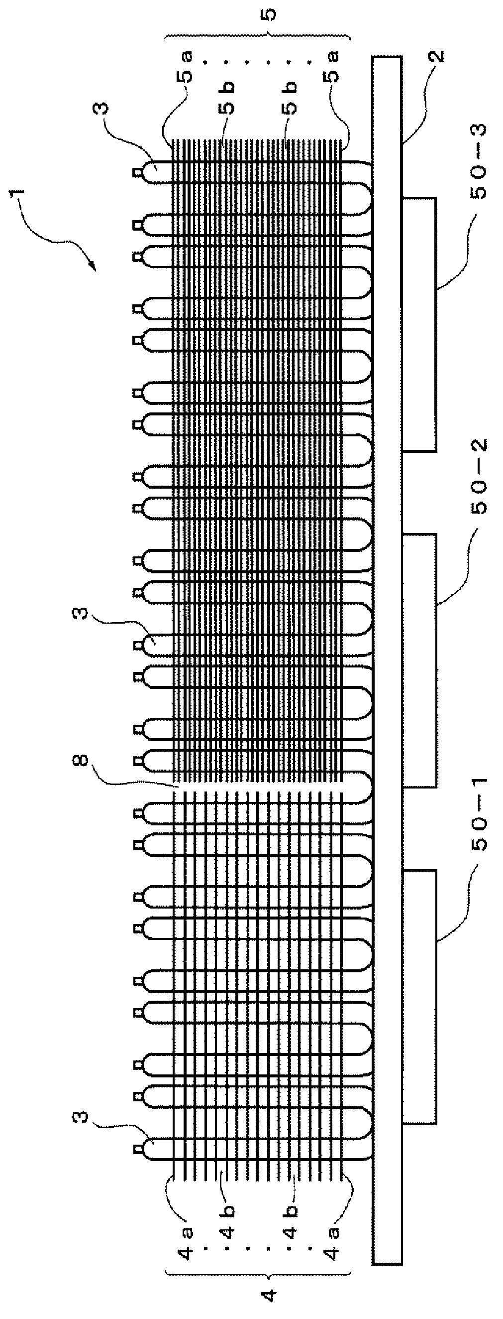
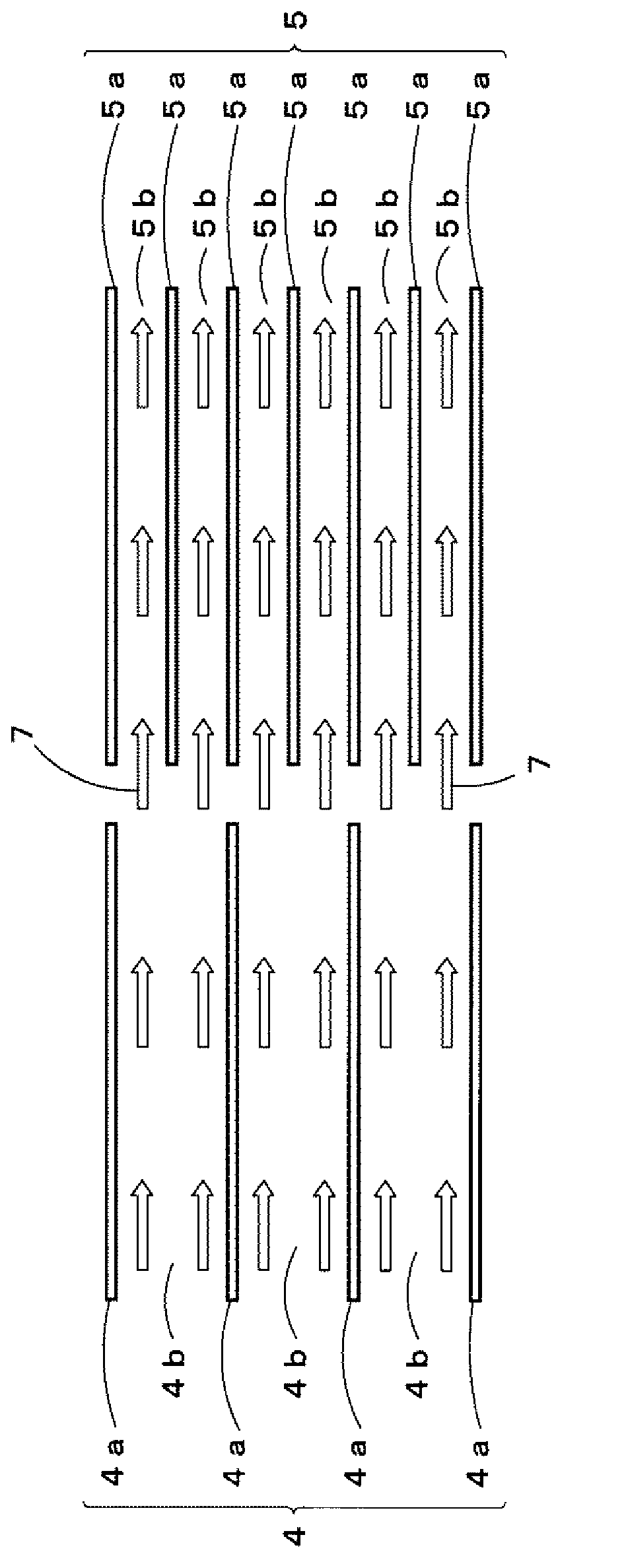
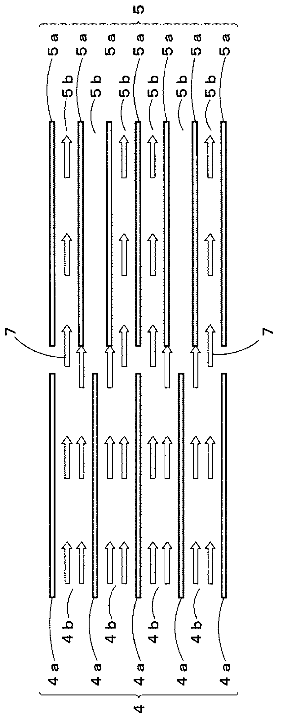
[0036] Hereinafter, a cooling device according to a first embodiment of the present invention will be described using the drawings. Such as figure 1 As shown, the cooling device 1 of the first embodiment of the present invention is a heat pipe cooling device, including a flat heat receiving block 2, and a plurality of U-shaped heat pipes installed in the vertical direction on the surface of the heat receiving block 2 3. The first cooling fin group 4 and the second cooling fin group 5 installed on the heat pipe 3 . The first cooling fin group 4 includes a plurality of ( figure 1 17 among them) the first fin 4a, the first fin 4a is a rectangular thin plate. The second cooling fin group 5 includes a plurality of ( figure 1 33 among them) the second fin 5a, the second fin 5a is a rectangular thin plate.

[0037] And, on the side that heat pipe 3 is not installed, i.e. the back side of heat receiving block 2, figure 1 From left to right, thermally connect the body to be co...


PUM


Abstract

Provided is a cooling device wherein the cooling capability on the leeward side is improved without increasing the number of installed cooling fins or the airflow of cooling air. A cooling device is provided with a heat-receiving block thermally connected to a heater element; and a group of cooling fins including a plurality of fins thermally connected to the heat-receiving block such that the flow of cooling air is set in parallel with the heat-receiving block, wherein a plurality of the groups of cooling fins is arranged longitudinally along the flow direction of the cooling air, and of the plurality of the groups of cooling fins, the fin pitch of the groups of cooling fins arranged on the windward side of the cooling air is larger than the fin pitch of the groups of cooling fins arranged on the leeward side of the cooling air.

Description

technical field [0001] The present invention relates to a cooling device for cooling heating elements by forced air cooling, and more specifically, to a cooling device for cooling electrical components such as power conversion devices mounted on mobile tools such as railway vehicles, aircrafts, and ships by forced air cooling. Background technique [0002] As an existing cooling device, such as Figure 14 The electrical component cooling device (hereinafter, referred to as a conventional example) within the housing shown. This prior example includes: a plate-shaped heat receiving block 42, a plurality of heat pipes 43 that are vertically arranged on the surface of the heat receiving block 42 and are U-shaped in side view, and a heat pipe 43 that is installed to the heat pipe 43 in a direction parallel to the heat receiving block 42. The heat radiation fin group 44 of the plurality of fins 44a is formed such that the pitch between the fins 44a is equal in any part (Patent Doc...

Claims


Application Information

Patent Timeline
Patent Type & Authority Applications(China)
IPC IPC(8): H05K7/20H01L23/427H01L23/467
CPCH01L23/467F28D15/0275F28F3/022H01L23/3672H01L23/427F28F1/32F28F2215/04F28D1/00F28D15/0266H01L2924/0002H05K7/20218H05K7/2039H01L2924/00
Inventor 深井宽之桥本信行山田裕池田匡视岛田守
Owner FURUKAWA ELECTRIC CO LTD
Why Eureka
Try Eureka