
Honeycomb structure

a honeycomb and structure technology, applied in the field of honeycomb structure, can solve the problems of reducing the entire strength of the honeycomb structure, and reducing the thickness of the partition walls, so as to suppress the weight and heat capacity from being increased, increasing the entire strength and anti-erosion capability, and suppressing the pressure loss

Active Publication Date: 2012-10-25
DENSO CORP
View PDF2 Cites 16 Cited by
  • Summary
  • Abstract
  • Description
  • Claims
  • Application Information

AI Technical Summary

Benefits of technology

[0013]It is therefore desired to provide a honeycomb structure capable of increasing an entire strength and anti-erosion capability and capable of suppressing a pressure loss and an entire weight (as a heat capacity) from being increased.
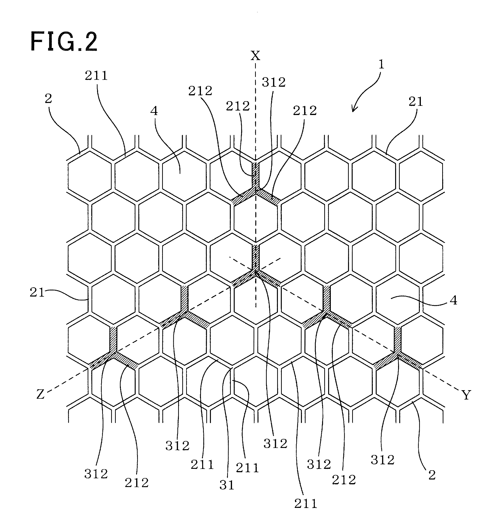
[0015]In the honeycomb structure having the improved and novel structure according to the exemplary embodiment of the present invention, three partition walls are joined to each other at a corresponding intersection point. At least some of the intersection points are the strength reinforcement intersection points. Some of the intersection points are the strength reinforcement intersection points. That is, three strength reinforcement sides as the strength reinforcement partition walls are joined to each other at the corresponding strength reinforcement intersection point. Each of the strength reinforcement sides has a thickness which is thicker than a thickness of each of sides. The other sides (namely, other than the strength reinforcement sides) as basic partition walls are joined at a corresponding basic intersection point (not at a strength reinforcement intersection point). This structure increases the entire strength of the honeycomb structure.
[0016]The formation of the strength reinforcement intersection points and the strength reinforcement sides (which are joined at the corresponding strength reinforcement intersection point) make it possible to increase the entire strength of the honeycomb structure. Further, because the strength reinforcement sides as the strength reinforcement partition walls having a thick thickness and the strength reinforcement intersection points are formed in the honeycomb structure, it is possible for the improved structure of the honeycomb structure to suppress the generation of abrasion and damage (erosion phenomenon) caused by collision with foreign substances contained in exhaust gas. This makes it possible to increase the anti-erosion capability and the durability of the honeycomb structure.
[0019]The improved and novel structure of the honeycomb structure having the strength reinforcement sides and intersection points makes it possible to increase the entire strength and the anti-erosion capability and to suppress the pressure loss from being increased, and also to suppress the weight and heat capacity from being increased.
[0020]It is possible for the honeycomb structure with catalyst to suppress the pressure loss from being increased because the improved and novel structure of the honeycomb structure can suppress the cells from being clogged with catalyst. Catalyst is supported on the surface of the cells, namely, on the surface of the partition walls which form the cells. This makes it possible to prevent the exhaust gas purifying capability from being deteriorated or decreased. It is therefore possible for the present invention to provide speedy activation of catalyst which is supported on the surface of the cells in the honeycomb structure because of suppressing the increasing of the pressure loss, the weight (namely, the heat capacity) of the honeycomb structure.
[0021]The honeycomb structure having the improved and novel structure according to the present invention can increase and enhance the entire strength and the anti-erosion capability of the honeycomb structure, and suppress the pressure loss and the entire weight from being increased.

Problems solved by technology

The reduction of the entire weight of the honeycomb structure reduces a heat capacity of the honeycomb structure.
However, the reduction of the thickness of the partition walls decreases the entire strength of the honeycomb structure.
Still further, the reduction of the thickness of the partition walls causes erosion phenomenon in the honeycomb structure.
The collision with foreign substance contained in exhaust gas would generate abrasion of and damage to the honeycomb structure, and thereby would decrease the durability of the honeycomb structure.
However, because a gap between adjacent cells in the reinforcement areas becomes narrow, catalyst is easily clogged between the adjacent cells, and this structure increases a pressure loss.
The catalyst clogged in the ells increases the entire weight of the honeycomb structure.

Method used


Image

  • Honeycomb structure
  • Honeycomb structure
  • Honeycomb structure

Examples


first exemplary embodiment

[0091]A description will be given of the honeycomb structure 1 according to a first exemplary embodiment of the present invention with reference to FIG. 1 to FIG. 9.

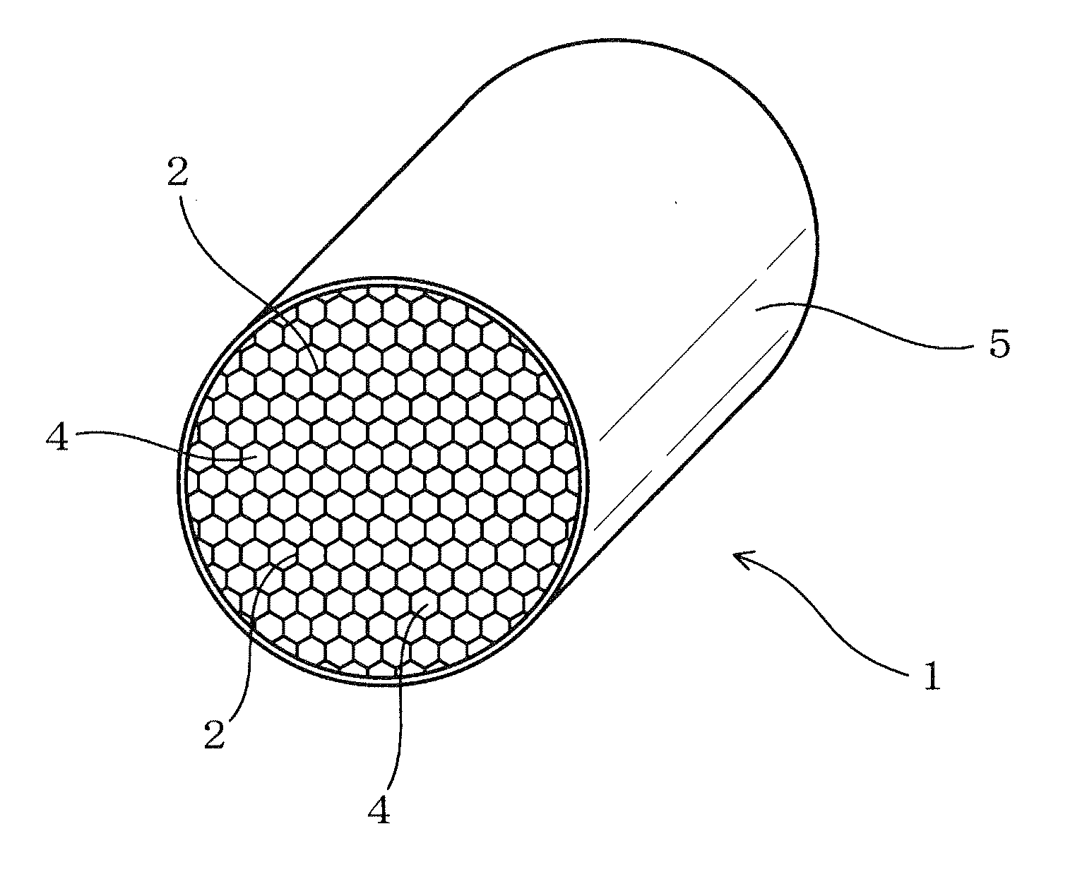
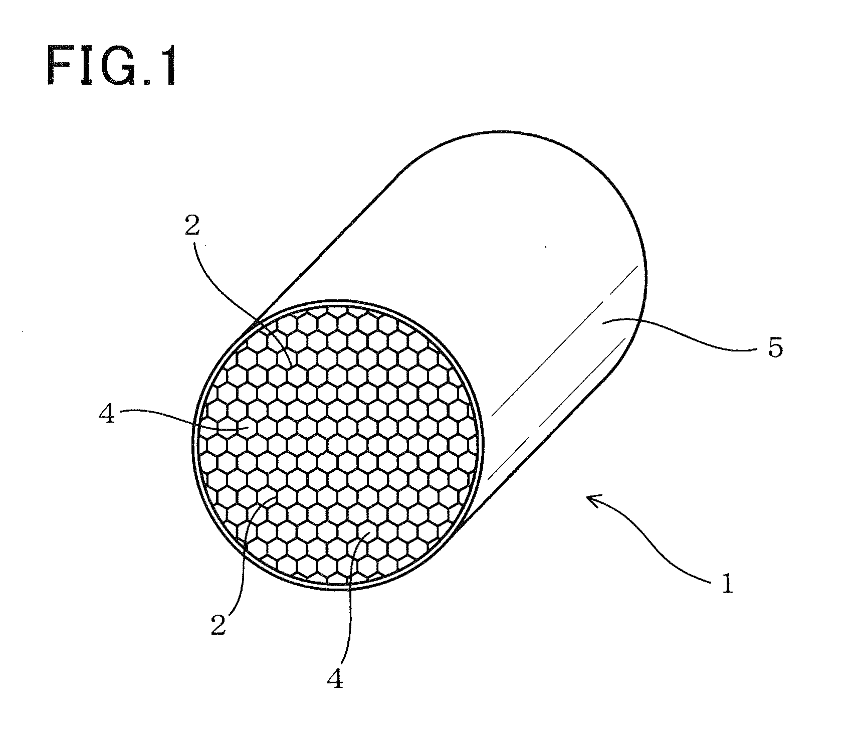
[0092]FIG.1 is a perspective view showing the entire of the honeycomb structure 1 according to the first exemplary embodiment of the present invention. FIG. 2 is a view showing a cross section of the honeycomb structure 1 having a plurality of cells and partition walls according to the first exemplary embodiment of the present invention. FIG. 3 is a view showing a radial cross section of the honeycomb structure 1 according to the first exemplary embodiment of the present invention.

[0093]As shown in FIG. 1, FIG. 2 and FIG. 3, the honeycomb structure 1 has a plurality of cells 4 and a cylindrical outer peripheral wall. Each of the cells 4 has a hexagonal shape (or the hexagonal cells 4). Each hexagonal cell 4 is surrounded by six partition walls 2. The partition walls 2 are arranged in a hexagonal lattice pattern on the en...

second exemplary embodiment

[0144]A description will be given of a second exemplary embodiment of the present invention with reference to FIG. 10 to FIG. 18. The secondary exemplary embodiment executes the evaluation of characteristics (the pressure loss, the anti-erosion capability, and the function to purify exhaust gas) of various types of honeycomb structures which contain the honeycomb structure 1 according to the first exemplary embodiment previously described.

[0145]The secondary exemplary embodiment prepared three honeycomb structures (as test samples E1, E2 and E3) and two conventional structures (as comparison samples C1 and C2).

[0146]The test samples E1, E2, E3 and the comparison samples C1 and C2 have a basis structure, for example the structure shown in FIG. 1. That is, each of the test samples E1, E2, E3 and the comparison samples C1 and C2 is composed of a plurality of the cells 4 and the cylindrical outer peripheral wall 5. The cell 4 is surrounded by the partition walls 2. The partition walls 2...

third exemplary embodiment

[0174]A description will be given of a third exemplary embodiment of the present invention with reference to FIG. 19A, FIG. 19B, FIG. 19C and FIG. 20. The third exemplary embodiment executes the evaluation of anti-erosion capability as one of the characteristics of the honeycomb structure.

[0175]FIG. 19A, FIG. 19B and FIG. 19C are views showing a cross section of each of comparison samples A11 and A12 and a test sample A13 used in the third exemplary embodiment of the present invention.

[0176]As shown in FIG. 19A, FIG. 19B and FIG. 19C, the third exemplary embodiment prepared and used three samples A11, A12 and A13.

[0177]As shown in FIG. 19A, the comparison sample A11 is a honeycomb structure 91-2 having a structure in which one strength reinforcement side 212 (designated by the solid lines) in three sides of the partition walls, which are joined at the corresponding intersection point 31 of the three partition walls, is a strength reinforcement side 212 of the three strength reinforc...


PUM

PropertyMeasurementUnit
lengthaaaaaaaaaa
outer diameteraaaaaaaaaa
thicknessaaaaaaaaaa

Abstract

A honeycomb structure has hexagonal cells surrounded by partition walls and a cylindrical outer peripheral wall covering the honeycomb structure. The partition walls have sides and intersection points. Six sides form a hexagonal cell. Three sides as the partition walls are joined to each other at a corresponding intersection point. The sides are divided into sides of basic partition walls and strength reinforcement sides as strength reinforcement partition walls. The strength reinforcement partition wall is thicker than the basic partition wall. Three strength reinforcement sides are joined at a corresponding strength reinforcement intersection point. Each strength reinforcement side in one group joined at one strength reinforcement intersection point is not connected continuously to each strength reinforcement side in another group joined at another strength reinforcement intersection point. The strength reinforcement intersection points are arranged on an entire surface of a radial cross section of the honeycomb structure.

Description

CROSS-REFERENCE TO RELATED APPLICATION[0001]This application is related to and claims priority from Japanese Patent Application No. 2011-94445 filed on Apr. 20, 2011, the contents of which are hereby incorporated by reference.BACKGROUND OF THE INVENTION[0002]1. Field of the Invention[0003]The present invention relates to a honeycomb structure capable of supporting catalyst which purifies exhaust gas emitted from an internal combustion engine of motor vehicles.[0004]2. Description of the Related Art[0005]Honeycomb structures have been known and also widely used in exhaust gas purifying systems mounted to an internal combustion engine of a motor vehicle. Such a honeycomb structure supports catalyst therein, namely, on the surface of partition walls forming a plurality of cells in order to purify exhaust gas emitted from the internal combustion engine of a motor vehicle. The honeycomb structure has a structure composed in general of a plurality of cells and a cylindrical outer peripher...

Claims


Application Information

Patent Timeline
Patent Type & Authority Applications(United States)
IPC IPC(8): B32B3/12
CPCB01D46/247Y10T428/24165B01J35/10F01N2330/06F01N2330/34F01N2330/48F01N3/2825B01J23/464B01D53/92B01J35/04B01J35/1076C04B38/0006B01D53/94B01D2255/1021B01D2255/1023B01D2255/1025B01D2255/9202B01D2255/9205B01D46/2466Y10T428/24149B01D46/2474C04B35/195C04B38/0009C04B2111/00793C04B2111/0081B01D46/2482B01D46/2484B01D46/2492B01J35/56B01J35/657C04B38/0051C04B38/0054C04B38/0074B01D46/2429B01D46/2425B01J35/60
Inventor HIRATSUKA, YUUICHI
Owner DENSO CORP
Learn More