Air conditioning register

a technology of air conditioner and register, which is applied in the direction of vehicle components, vehicle heating/cooling devices, transportation and packaging, etc., can solve the problems of increasing pressure loss and noise generation, increasing pressure loss, and increasing noise generation, so as to increase the size of the rack in the teeth arranging direction (the longitudinal direction of the downstream fin), increase the ventilation resistance of the rack, and increase the effect of pressure loss

Active Publication Date: 2014-03-20
TOYODA GOSEI CO LTD
View PDF15 Cites 15 Cited by
  • Summary
  • Abstract
  • Description
  • Claims
  • Application Information

AI Technical Summary

Benefits of technology

[0009](2) According to the air conditioning register that is structured to close the ventilation passage by the upstream fins, the ventilation passage is closed when the upstream fins are tilted to a greater extent than those of the air conditioning register that is not structured to close the ventilation passage by the upstream fins. Therefore, the size of the rack in a teeth arranging direction (the longitudinal direction of the downstream fins) is increased.
[0010]Since the size of the rack increases in the face width direction and in the teeth arranging direction as described above, ventilation resistance by the rack is increased, so that the pressure loss is increased and the generation of noise is caused.
[0011]Accordingly, it is an objective of the present invention to provide an air conditioning register capable of suppressing pressure loss and generation of noise caused by a part for transmitting sliding operation of an operation knob to upstream fins.

Problems solved by technology

When the rack and the pinion are used to transmit the sliding operation of the operation knob to the upstream fins, like the air conditioning register described in Japanese Patent No. 4055693, problems such as an increase in pressure loss and generation of noise may be caused.
Since the size of the rack increases in the face width direction and in the teeth arranging direction as described above, ventilation resistance by the rack is increased, so that the pressure loss is increased and the generation of noise is caused.

Method used


Image

  • Air conditioning register
  • Air conditioning register
  • Air conditioning register

Examples


Embodiment Construction

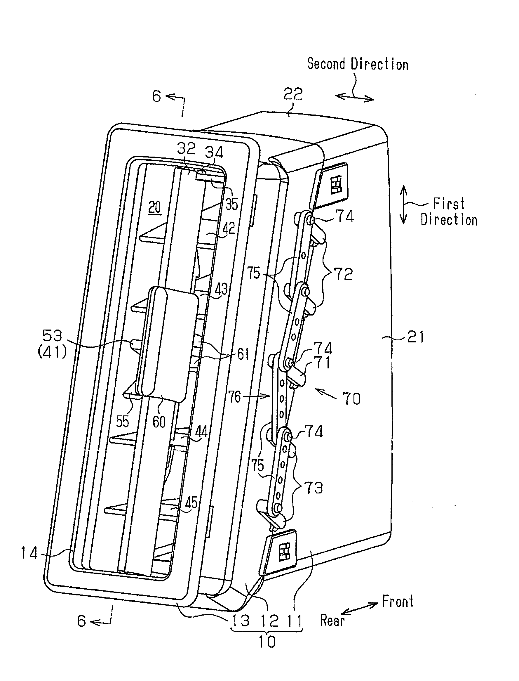
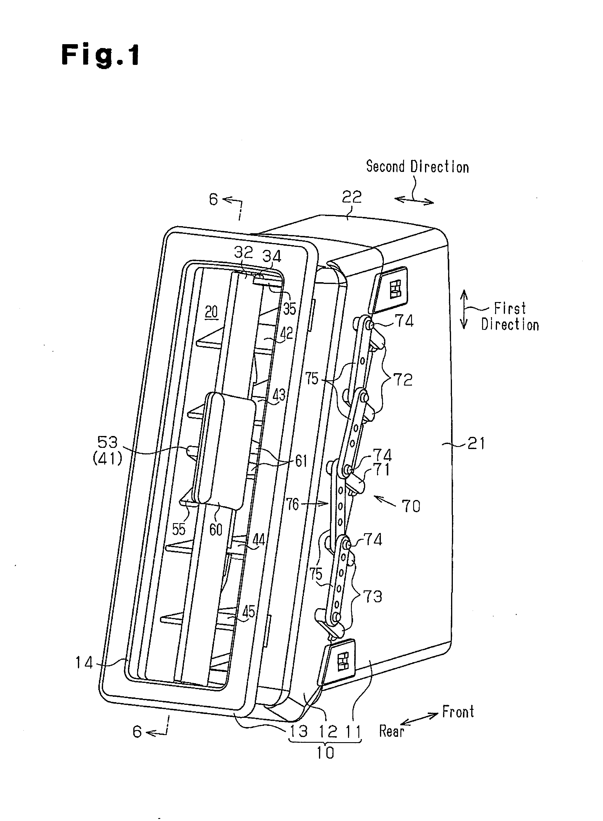
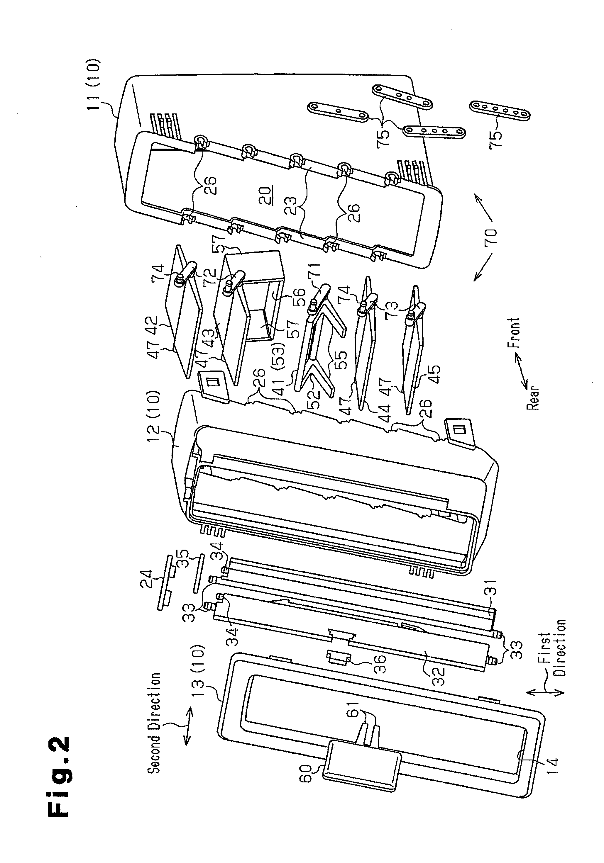
[0038]An air conditioning register according to one embodiment of the present invention will now be described with reference to FIG. 1 to FIG. 16B. The air conditioning register is used for vehicles. The air conditioning register has a thin shape of which the horizontal size is smaller than its vertical size.

[0039]In the following description, an explanation will be given by defining a travelling direction (a forward movement direction) of the vehicle as the front, a backward movement direction as the rear, and a height direction as a vertical direction. With regard to a vehicle lateral direction (a left-right direction), the right and the left are defined relative to the forward movement direction of the vehicle.

[0040]In a passenger compartment, an instrument panel is located in front of the front seats (a driver's seat and a passenger seat) of the vehicle. For example, the instrument panel is equipped with the air conditioning registers of this embodiment at its center portion and...


PUM


Abstract

An air conditioning register includes a downstream fin, primary upstream fins, a secondary upstream fin, and an operation knob slidably attached onto the downstream fin. The operation knob sandwiches a shaft of the secondary upstream fin. The air conditioning register has a link mechanism that includes arms and a coupling rod. The arms extend from pivots of the primary and secondary upstream fins in a direction orthogonal to the pivots, and have a pin at the tip of the arms. The coupling rod couples the respective pins. The distance between the pivot and the pin in the arm of the secondary upstream fin is longer than the distance between the pivot and the pin in the arm of each primary upstream fin. The coupling rod includes coupling portions, each of which couples the pins of an adjacent pair of the arms. Adjacent coupling portions are pivotally coupled.

Description

BACKGROUND OF THE INVENTION[0001]The present invention relates to an air conditioning register, which changes the flow direction of air for air conditioning transmitted from an air conditioner to be blown into a compartment by a plurality of fins and, more particularly, to an air conditioning register that has a structure for selectively opening and closing a ventilation passage by the fins.[0002]For example, Japanese Patent No. 4055693 discloses an air conditioning register for changing the flow direction of air for air conditioning transmitted from an air conditioner blown into a vehicle passenger compartment and that has a structure for selectively opening and closing a ventilation passage by fins.[0003]This air conditioning register includes a case, a plurality of downstream fins, a plurality of upstream fins, and an operation knob. The case has a cylindrical shape, and its inner space constitutes a ventilation passage for the air for air conditioning. Each of the plate-shaped d...

Claims


Application Information

Patent Timeline
Patent Type & Authority Applications(United States)
IPC IPC(8): B60H1/34
CPCB60H1/3421
Inventor TAKAI, HAJIMEOGURA, MITSUOSHIBATA, MINORUASANO, KENJI
Owner TOYODA GOSEI CO LTD
Why Eureka
Try Eureka