Apparatus for applying paste and method of applying paste

Inactive Publication Date: 2005-03-17
SHIBAURA MECHATRONICS CORP
View PDF4 Cites 42 Cited by
  • Summary
  • Abstract
  • Description
  • Claims
  • Application Information

AI Technical Summary

Benefits of technology

[0009] The object of the present invention is to provide a paste applying apparatus and a paste app

Problems solved by technology

However, although the above paste applying apparatus suppresses generation of dust by using a linear motor for moving the applying heads, it uses linear guides for movably support

Method used


Image

  • Apparatus for applying paste and method of applying paste
  • Apparatus for applying paste and method of applying paste
  • Apparatus for applying paste and method of applying paste

Examples


Embodiment Construction

[0026] An embodiment of the present invention is explained with reference to drawings.

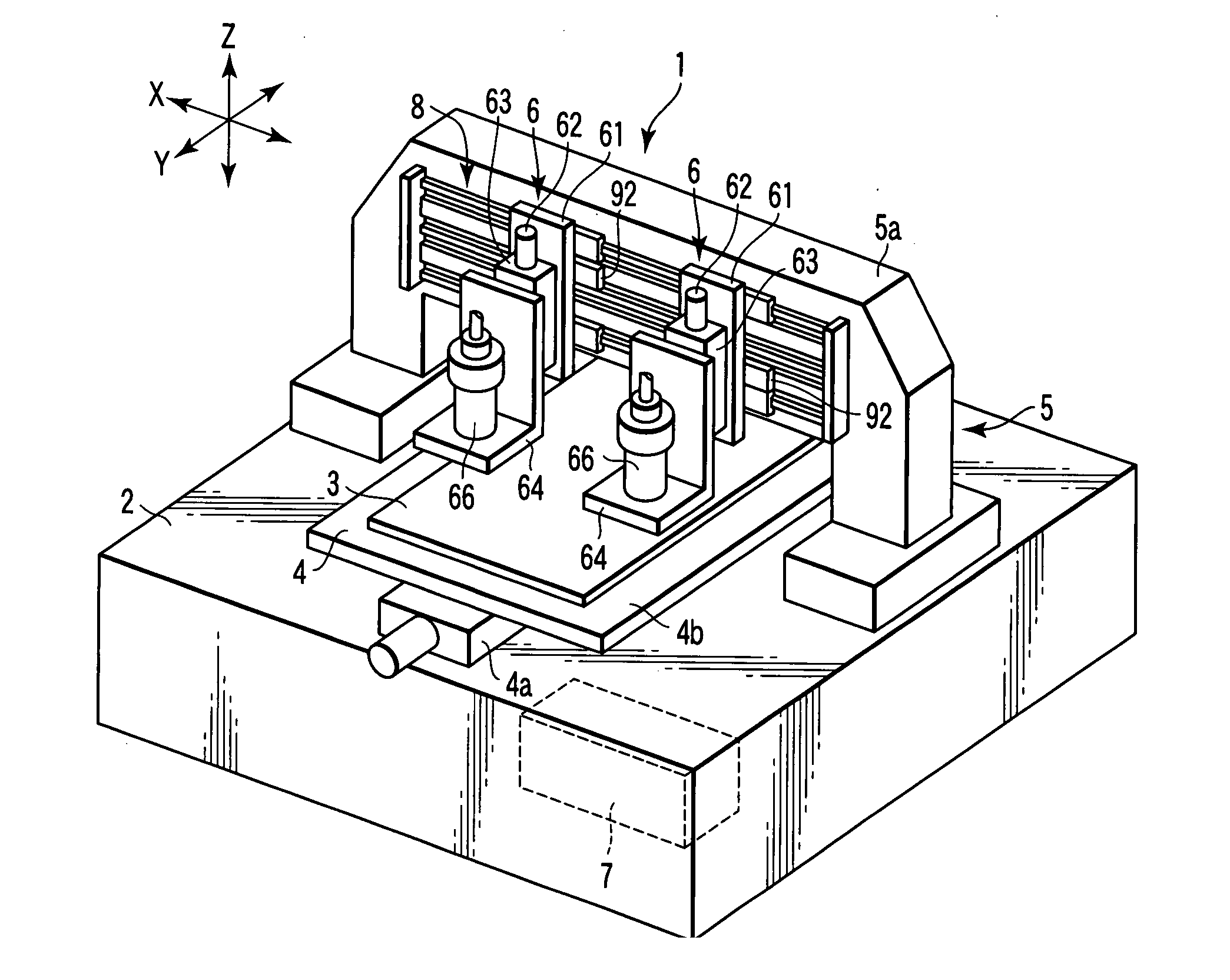
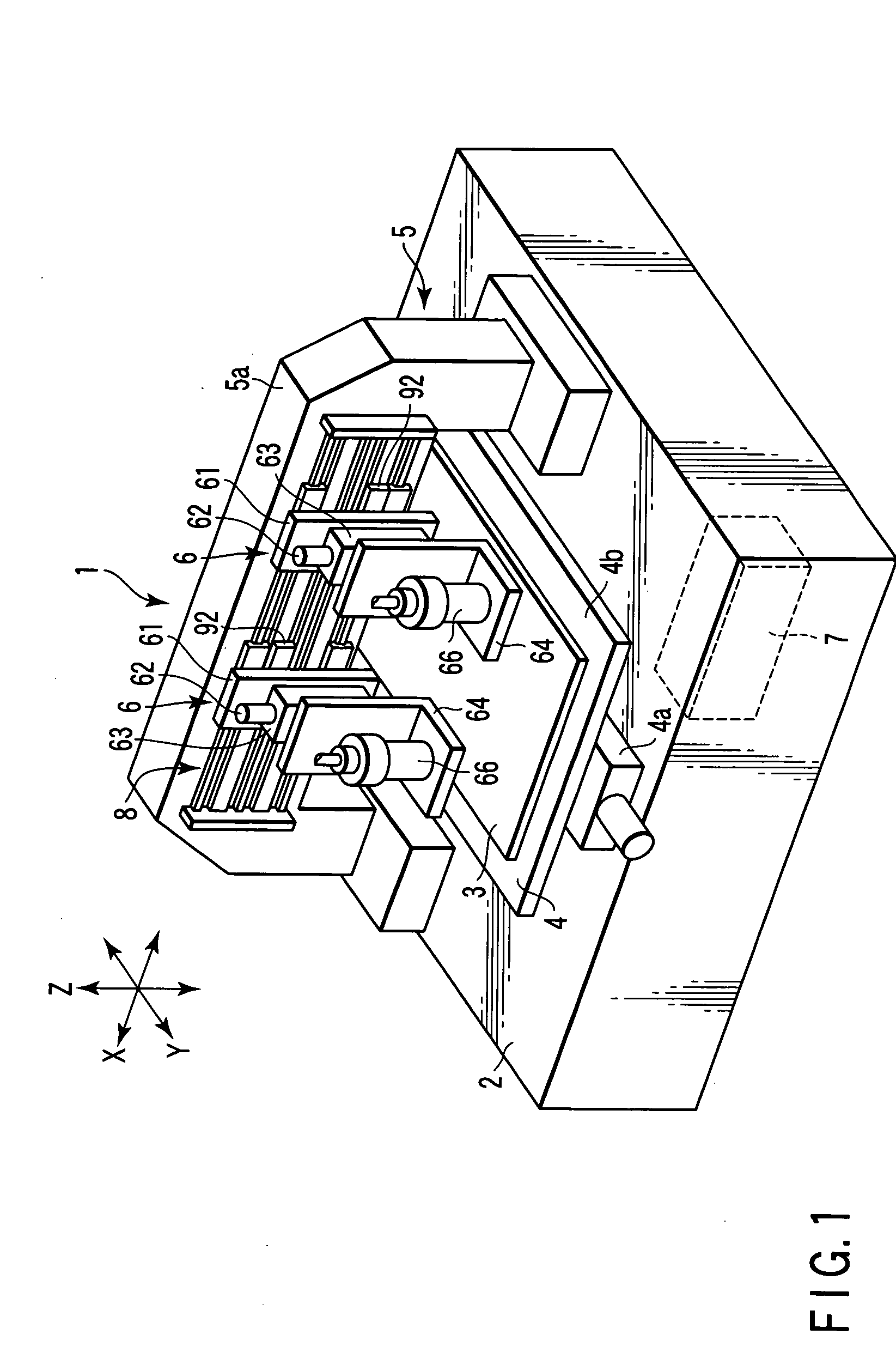
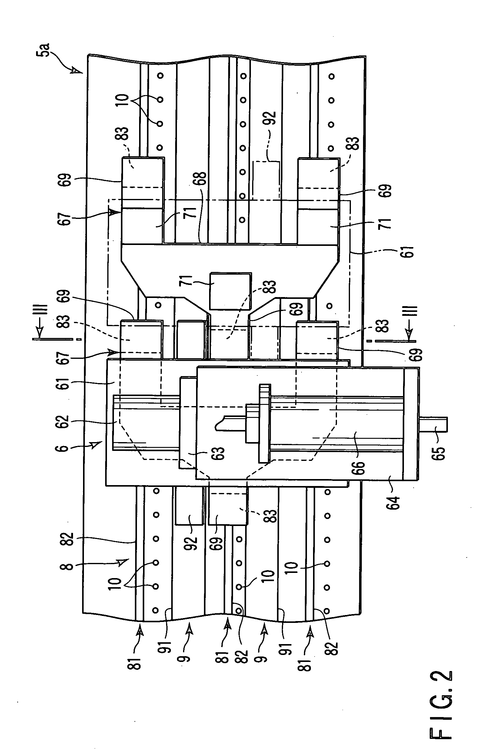
[0027]FIG. 1 is a perspective view of a structure of a paste applying apparatus according to the present invention, FIG. 2 is a front view of a structure of a main part of the paste applying apparatus shown in FIG. 1, FIG. 3 is a cross-sectional view taken along line III-III of FIG. 2, FIG. 4 is a diagram illustrating a structure of a control unit in the paste applying apparatus shown in FIG. 1, and FIGS. 5 and 6 are diagrams for explaining operation of the paste applying apparatus shown in FIG. 1.

[0028] In FIG. 1, a paste applying apparatus 1 comprises a base 2, a stage 4 which is disposed on the base 2 and on which a substrate 3 is placed, a gate-shaped frame 5 fixed on the base 2, two applying heads 6 which are movably supported by a beam member 5a of the frame 5, and a control unit 7 disposed in the base 2.

[0029]FIG. 1 shows X, Y and Z directions by arrows. The stage 4 is disposed on the bas...


PUM


Abstract

An applying apparatus, which applies paste in a preset pattern to a substrate, includes a stage having a holding surface on which the substrate is placed, a beam member extending above the stage in a direction along the holding surface, a moving device which relatively moves the beam member and the stage in a direction along the holding surface and perpendicular to the extending direction of the beam member, a guide member provided on the beam member and along the extending direction of the beam member, an applying head which is supported by the guide member and movable along the guide member, and a plurality of suction nozzles which are provided along the guide member and suck air in the vicinity of the guide member.

Description

CROSS-REFERENCE TO RELATED APPLICATIONS [0001] This application is based upon and claims the benefit of priority from prior Japanese Patent Application No. 2003-65816, filed Mar. 11, 2003, the entire contents of which are incorporated herein by reference. BACKGROUND OF THE INVENTION [0002] 1 Field of the Invention [0003] This invention relates to a paste applying apparatus and a method of applying paste, for applying paste in a preset pattern on a substrate. [0004] 2 Description of the Related Art [0005] In conventional paste applying apparatuses which apply paste in a preset pattern on a substrate, a frame which is movable by a linear motor in a predetermined direction is disposed above a stage on which a substrate is placed. The frame is provided with a plurality of applying heads which are movable in a direction perpendicular to the moving direction of the frame. [0006] By the above structure, it is possible to apply paste in a plurality of desired patterns on a substrate simulta...

Claims


Application Information

Patent Timeline
IPC IPC(8): B05C5/02B05C5/00
CPCB05C5/027A01K1/03
Inventor SHIMODA, NORIAKI
Owner SHIBAURA MECHATRONICS CORP
Why Eureka
Try Eureka