
Fender support for a motor vehicle

a technology for fender support and motor vehicles, applied in the direction of monocoque construction, superstructure subunits, understructures, etc., can solve the problems of reducing the amount of energy that is absorbed, affecting the position of the fender support, and insufficient prior art support, so as to effectively dampen the impact of the head of the pedestrian. , the effect of positioning easily and accurately

Inactive Publication Date: 2005-03-17
CO PLASTIC OMNIUM
View PDF21 Cites 63 Cited by
  • Summary
  • Abstract
  • Description
  • Claims
  • Application Information

AI Technical Summary

Benefits of technology

The present invention provides a new fender support part for a motor vehicle that can easily and accurately position the fender on the vehicle, and provide effective damping of the impact of a pedestrian's head. The support part has a metal core with ribs that serve both stiffening and absorption functions, and can be easily mounted on the vehicle's structure while providing effective protection against impact. The support part can be overmolded onto the metal core, and has a bottom portion that can accommodate differences in space between the vehicle structure and the top edge of the fender. The support part can be designed to provide Y-direction stiffness and Z-direction absorption, and can also have additional functions such as providing stability and damping the impact of the fender.

Problems solved by technology

However, those prior art supports are inadequate when it comes to impacts against the heads of pedestrians.
If the impact of the head lies in the middle region of the hood, then indentation of the hood can suffice to absorb enough energy to preserve the pedestrian's head, providing other difficulties specific to hood impacts are properly handled, which difficulties lie outside the ambit of the present description.
In contrast, if the corresponding impact zone coincides with the top edge of a fender, there is a risk that the intrinsic stiffness of the fender rim, plus that of the hood rim which is adjacent to the fender rim, will reduce the amount of energy that is absorbed and will lead to the pedestrian's head being decelerated too quickly.

Method used


Image

  • Fender support for a motor vehicle
  • Fender support for a motor vehicle
  • Fender support for a motor vehicle

Examples


Embodiment Construction

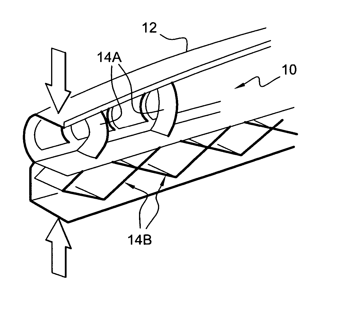
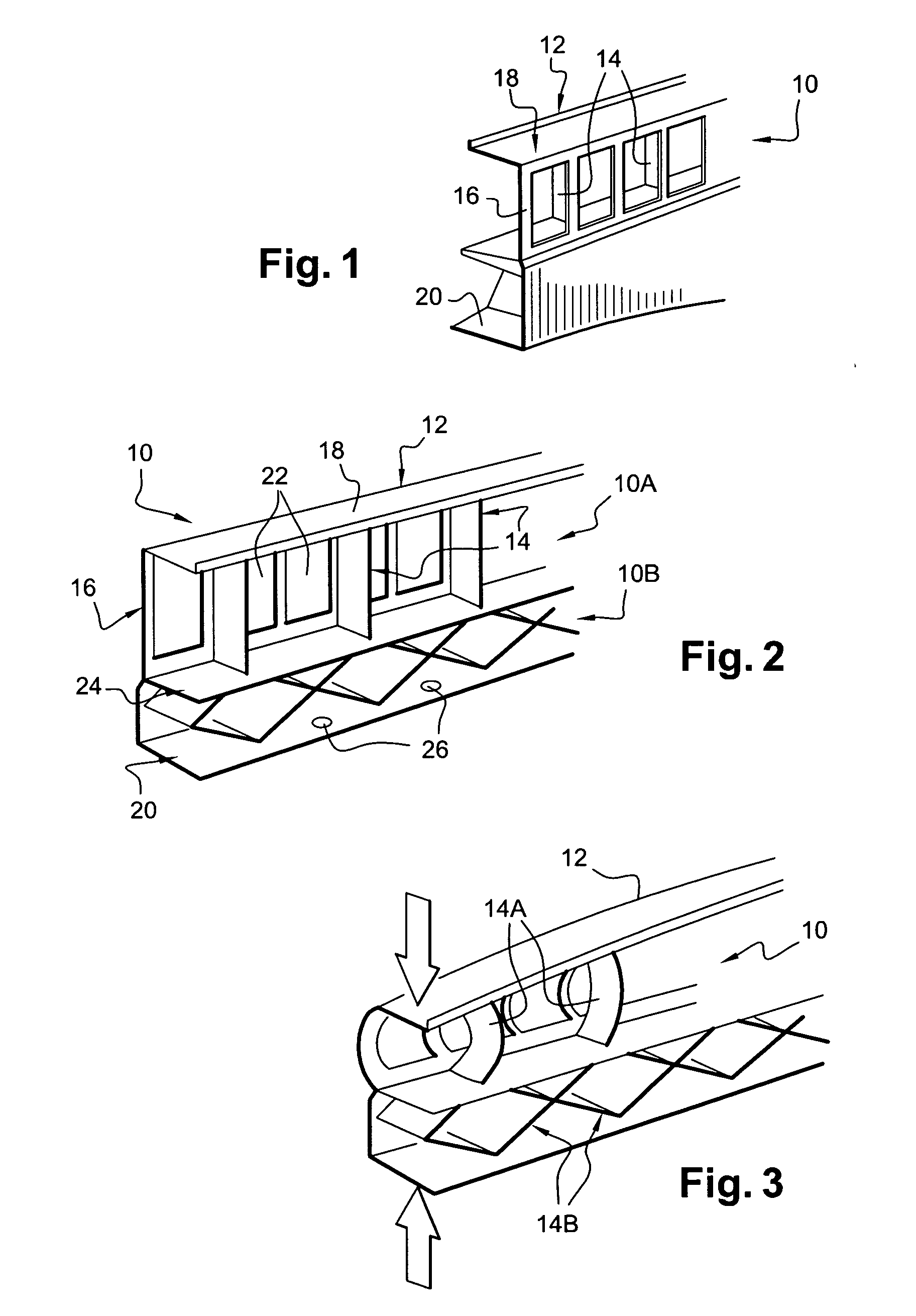
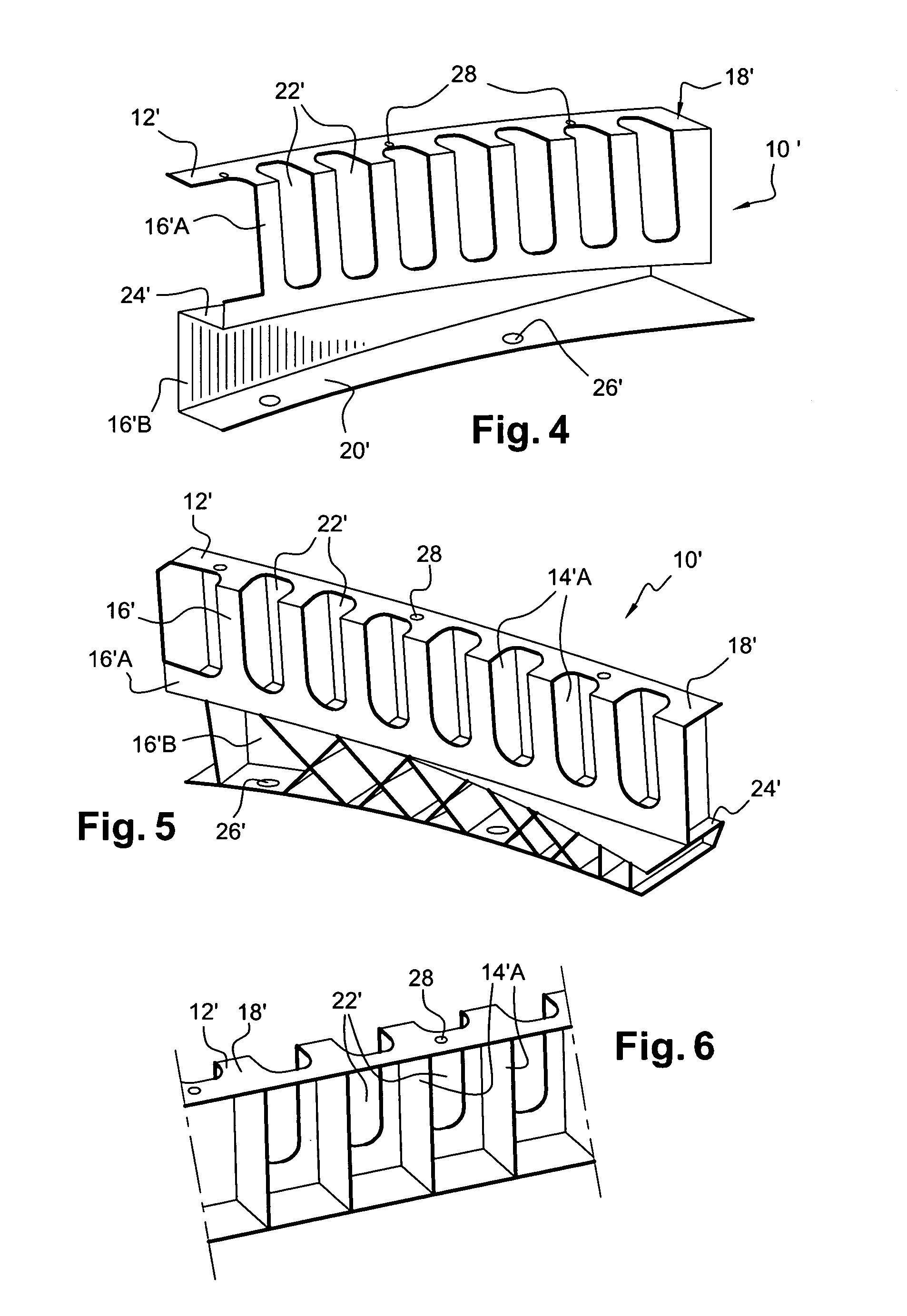
[0044] The support shown in the drawings, given overall reference 10, is of hybrid structure, being constituted by a core 12 of sheet metal having a C-shaped vertical section (as seen in FIG. 2) and by ribs 14 made of thermoplastic material.

[0045] More precisely, the metal core 12 comprises a vertical wall 16 (vertical in the orientation of the drawing) and two substantially horizontal rims 18 and 20 (horizontal in the orientation of the drawing) extending perpendicularly to the vertical wall 16 in the longitudinal direction of the support 10.

[0046] The support 10 is functionally subdivided into two portions 10A and 10B that are situated in the example shown above and below a setback, even though this coincidence is fortuitous.

[0047] The top portion 10A has rectangular openings 22 formed through the vertical wall 16. The function of these openings 22 is to reduce the stiffness in the Z-direction of the metal core 12 in this top portion 10A so as to make it easier to form in the e...


PUM


Abstract

The motor vehicle fender support comprises a metal core with a top portion provided with fasteners for fastening to a fender. The top portion is provided with ribs arranged to stiffen it in the event of stress being directed in the transverse direction, and to buckle in the event of downwardly-directed impacts, when the fender support is mounted on the vehicle. The metal core also includes openings seeking to reduce its stiffness so as to satisfy predefined deceleration criteria. The fender support also comprises a rigid bottom portion designed to be fastened to the structure of the vehicle.

Description

[0001] The present invention relates to a fender support for a motor vehicle. BACKGROUND OF THE INVENTION [0002] It is known to secure a motor vehicle fender to the structure of the vehicle via a support, sometimes referred to as a fender support, which support is itself secured to the rigid structure of the vehicle, itself referred to as the blank body. [0003] Known supports can be fasteners having additional functions such as positioning the fender, the ability to withstand expansion, fusibility in the event of an impact in order to preserve the fender, or indeed backing for the fender so as to increase its dent resistance. [0004] An example of a fender support provided in the state of the art is described in document EP 0 839 704. On its outside face that is to receive a fender, that support carries an array of ribs that matches the inside shape of the fender. [0005] However, those prior art supports are inadequate when it comes to impacts against the heads of pedestrians. [0006]...

Claims


Application Information

Patent Timeline
Patent Type & Authority Applications(United States)
IPC IPC(8): B62D25/08B60R21/02B60R21/34B62D21/15B62D25/16B62D29/00
CPCB60R21/34B60R2021/343B62D29/004B62D25/163B62D29/001B62D21/15
Inventor ROUX, JEAN-PIERREPIERROT, FREDERICANDRE, GERALDCHERON, HUGUES
Owner CO PLASTIC OMNIUM
Learn More