
Liquid discharger and liquid discharge adjustment method

Inactive Publication Date: 2005-03-17
SONY CORP
View PDF3 Cites 32 Cited by
  • Summary
  • Abstract
  • Description
  • Claims
  • Application Information

AI Technical Summary

Benefits of technology

[0018] An object of the present invention is to provide a liquid discharger capable of controlling the discharge direction of a droplet and preventing a decrease in image quality, and a liquid discharge adjusting method capable of easily adjusting the discharge direction of a droplet.
[0020] In this liquid discharger, the discharge controlling means drives each pressure-generating element based on a color tone detection signal in accordance with the color tone of the droplet-landing region detected by the color tone detection means. In this way, the discharge angle when a droplet is discharged from the discharging outlet can be adjusted to an angle of which a predetermined color tone (i.e., color density and brightness) for the droplet-landing region on the object can be obtained.
[0024] In this way, according to the present invention, the image quality can be easily optimized even when the thickness of the object changes, the discharge angle changes due to the environment, or the type of liquid discharged onto the object changes.
[0025] According to the present invention, individual differences, such as differences in the distance from the discharging outlet to the object or differences in the discharge means, may be easily adjusted.

Problems solved by technology

Even when a servo motor is used, as described above, expansion and contraction of an image may be prevented, but slight unevenness in the color tone (i.e., unevenness in the density of the color) caused by an instantaneous change in the timing of the ink landing on the recording paper can not be prevented.
Consequently, when a series of ink droplets are discharged, the ink droplets will land close together in some parts and far apart in other parts, causing change in the concentration of the color that appears as unevenness in the density of the color or white stripes.
For this reason, if the discharge direction of the ink discharged from each of the nozzles on the line is not stabilized, a faulty nozzle having a discharge direction different from the other normal nozzles will cause uneven color density and stripes.
Overlapping the ink, however, may prevent uneven color density and white stripes, but, at the same time, may increase the printing time and the amount of ink used for printing.
Accordingly, the printed image cannot be improved and degradation of the image cannot be prevented.
When this distance changes, the landing point of the ink droplet also changes, making it difficult to improve the printed image and to prevent degradation of the printed image.
In this method, however, much equipment including measuring instruments and time are required to calculate the heating value of each heating resistor for discharging ink at a predetermined discharge angle.
The structure of the system also becomes large, and reducing the size, weight, and energy consumption becomes difficult.

Method used


Image

  • Liquid discharger and liquid discharge adjustment method
  • Liquid discharger and liquid discharge adjustment method
  • Liquid discharger and liquid discharge adjustment method

Examples


Embodiment Construction

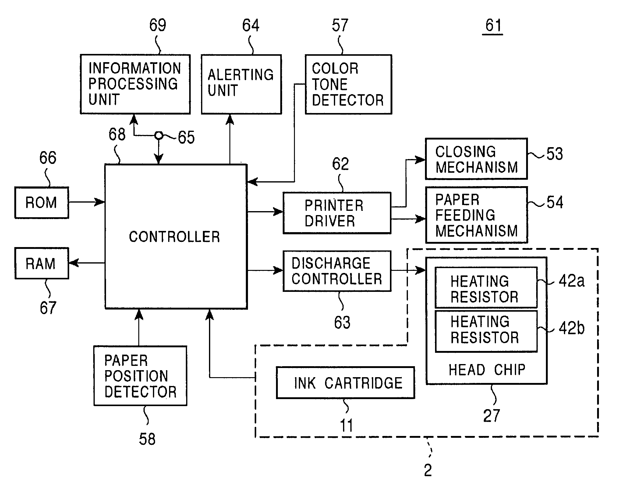
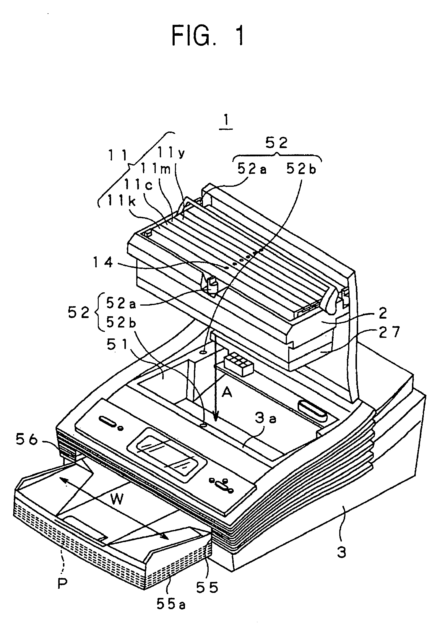
[0050] A liquid discharger and liquid discharge adjustment method according to the present invention will now be described by referring to the drawings. An inkjet printer (hereinafter referred to as a ‘printer’) 1, as illustrated in FIG. 1, is for printing images and text on a sheet of recording paper P delivered in a predetermined direction by discharging ink onto the sheet of recording paper P. The printer 1 is a line printer having ink discharging outlets (nozzles) aligned substantially linearly across the printing width of the sheet of recording paper P in the direction indicated by an arrow W in FIG. 1, which is the width direction of the sheet of recording paper P.

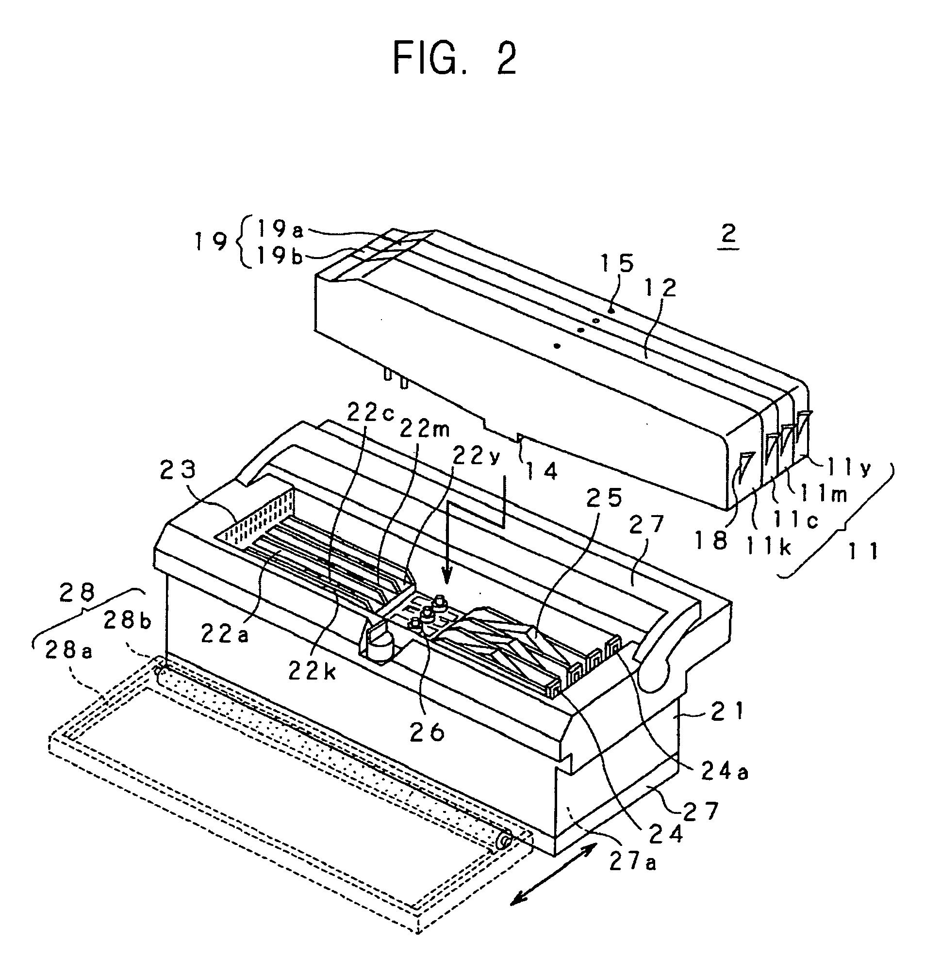
[0051] The printer 1 includes an inkjet printer head cartridge (hereinafter referred to as a head cartridge) 2 for discharging ink 4 (refer to FIG. 3) stored in ink cartridges 11y, 11m, 11c, and 11k and a printer body 3 holding the head cartridge 2. The head cartridge 2 is removable from the printer body 3, and the ...


PUM


Abstract

Since the pulse currents supplied to a pair of heating resistors can be controlled at once based on a color signal from a color tone detector, the discharge angle of ink droplets can be easily adjusted to an angle that provides a predetermined color tone.

Description

BACKGROUND OF THE INVENTION [0001] 1. Field of the Invention [0002] The present invention relates to a liquid discharger that discharges a droplet of pressurized liquid from an outlet onto an object by pressurizing the liquid with a force generated by a pressure-generating element and a method for adjusting the discharge. [0003] 2. Description of the Related Art [0004] As a liquid discharger, an inkjet printer for recording images and text is known. An inkjet printer is advantageous in that the operational cost is low, the size of the apparatus is small, and producing a colored image is easy. The ink of an inkjet printer is stored in an ink cartridge for each color, such as yellow, magenta, cyan, and black, and is supplied to ink chambers in a printer head. [0005] In such an inkjet printer, the ink supplied to the ink chambers is pressurized by a pressure-generating element, such as a heating resistor, disposed inside the ink chamber and, then, is discharged from a minute ink outlet...

Claims


Application Information

Patent Timeline
IPC IPC(8): B41J2/01B41J2/045B41J2/05B41J2/21
CPCB41J2/04505B41J2/04506B41J2/04526B41J2/2132B41J2/0458B41J2/04581B41J2/04533B41J2/04501
Inventor TAKENAKA, KAZUYASUUSHINOHAMA, IWAOIKEMOTO, YUICHIRO
Owner SONY CORP
Learn More