Light-emitting diode, one of the electrodes of which is a multilayer made of amorphous carbon

Active Publication Date: 2007-02-08
THOMSON LICENSING SA
View PDF5 Cites 6 Cited by
  • Summary
  • Abstract
  • Description
  • Claims
  • Application Information

AI Technical Summary

Benefits of technology

[0023] Thanks to the invention, the use of silane is avoided, thereby allowing these diodes to be fabricated more safely.
[0024] Preferably, if λ0 is the wavelength corresponding to the maximum intensity of the radiation emitted by the diode, for each of the series of two sublayers, if d1 is the thickness of the sublayer of index n1 and d2 is the thickness of the sublayer of index n2, then n1d1=n2d2=λ0/4, approximately. The multilayer therefore provides a multimirror effect, as already described in the prior art, especially an effect of the DBR (Diffracting Bragg Reflector) type.
[0025] Preferably, the number N of series of two sublayers of different indices is greater than 4. The multimirror effect provided by the multilayer electrode according to the invention can thus be more easily optimi

Problems solved by technology

Consequently, one drawback of this type of diode structure is that it requires the deposition of an electrode between the encapsulating multimirror layer and the organic electroluminescent layer, thereby complicating the process for fabricating the diode, especially when this encapsulating multimirror layer is in the lower position, as it is generally recommended to provide, in this case, contact ho

Method used


Image

  • Light-emitting diode, one of the electrodes of which is a multilayer made of amorphous carbon
  • Light-emitting diode, one of the electrodes of which is a multilayer made of amorphous carbon

Examples


Example

[0030] One exemplary embodiment of a diode panel according to the invention, here with a passive matrix, in which the diodes are interposed between an array of lower electrodes and an array of upper electrodes, will now be described.

[0031] A deposition mask, having apertures corresponding to the array of lower electrodes to be deposited, is applied to a substrate 1 made of transparent glass. The amorphous carbon multilayer 2 according to the invention is then deposited, through this mask, using a conventional vapour deposition technique, here based on methane and with no silane, under radiofrequency radiation (called PECVD). During deposition of amorphous carbon, the power of the radiofrequency radiation is varied, namely by alternating no radiofrequency power (i.e. CVD deposition), in order to obtain an amorphous carbon sublayer 21 of index n1=1.7, with 100 W power (PECVD deposition) in order to obtain a sublayer 22 of index n2=2.35. This alternation is repeated as many times as t...


PUM


Abstract

Diode comprising a substrate and an organic electroluminescent layer interposed between a lower electrode and an upper electrode, at least one of which electrodes is formed from a multilayer which is itself formed by the stack of adjacent sublayers made of amorphous carbon, having different refractive indices n1, n2. The amorphous carbon contains no added silicon, thereby making it possible to avoid using silane for the manufacture. The multilayer provides an electrode function, a multimirror function and an encapsulation function.

Description

[0001] This application claims the benefit, under 35 U.S.C. 119, of French patent application no. 0551796 filed 28 Jun. 2005. FIELD OF THE INVENTION [0002] The invention relates to organic light-emitting diodes and to panels comprising an array of such diodes, especially for illumination or for image display. DESCRIPTION OF THE PREFERRED EMBODIMENT 
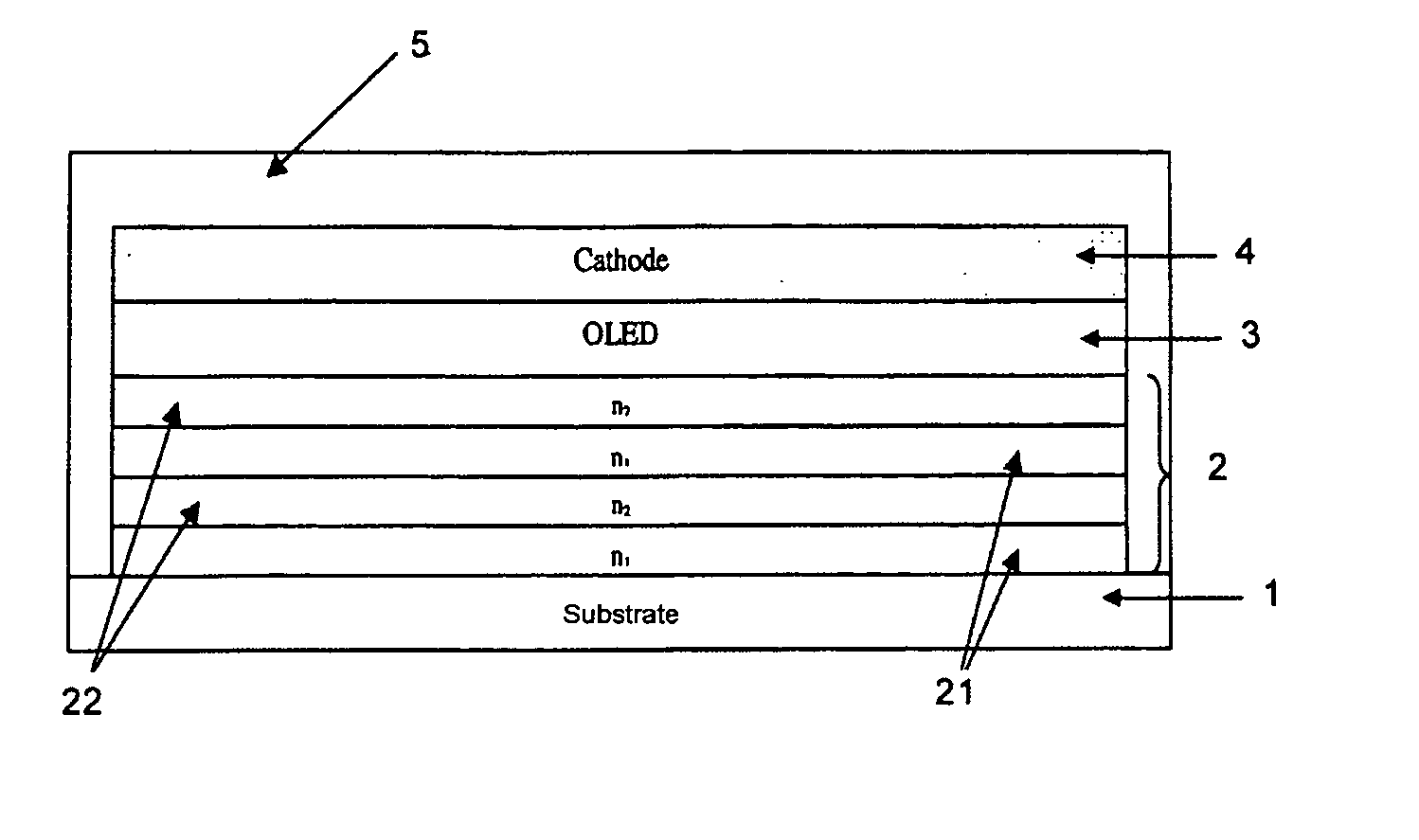
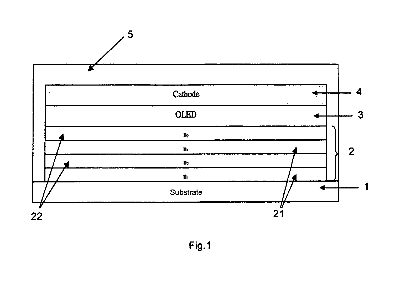
[0003] Document WO 03 / 052842 describes a light-emitting diode comprising a substrate, an organic electroluminescent layer that is interposed between a lower electrode in contact with the substrate and an upper electrode, and is capable of emitting radiation through at least one of said electrodes when a current is injected by these electrodes through the organic layer; according to that document, the diode also includes an encapsulation multilayer forming a mirror, which is interposed between the substrate and the lower electrode and / or is positioned above the upper electrode, which comprises at least one series formed from a sublayer of ...

Claims


Application Information

Patent Timeline
IPC IPC(8): H01L33/00
CPCH01L51/5206H01L51/5265H01L51/5221H10K50/816H10K50/822H10K50/8445H10K50/852
Inventor VAUFREY, DAVIDRACINE, BENOITFERY, CHRISTOPHE
Owner THOMSON LICENSING SA
Why Eureka
Try Eureka