Matching circuit for antenna and associated method
Active Publication Date: 2016-02-04
MEDIATEK INC
View PDF9 Cites 4 Cited by
Summary
Abstract
Description
Claims
Application Information
AI Technical Summary
This helps you quickly interpret patents by identifying the three key elements:
Problems solved by technology
Method used
Benefits of technology
[0006]To address issues difficult to be solved by antenna design, the invention discloses a low-cost antenna matching circuit to overcome unsatisfactory characteristics of antenna, e.g., antenna impedance which is difficult to be matched at multiple bands distributed over broad frequency range. The matching circuit according to the invention may be implemented by inexpensive tunable elements like diode(s) and/or switch(es), so as to reduce implement cost by avoiding use of expensive
Problems solved by technology
However, supporting bands over such broad frequency range is difficult to fulfill by traditional antenna design methodology.
Antenna design is also challenged by demand of compact antenna dimensions.
Modern electronic device is also required to inte
Method used
Image
Click on the blue label to locate the original text in one second.
Reading with bidirectional positioning of images and text.
Examples
Embodiment Construction
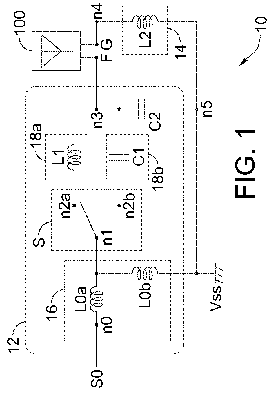
[0022]Please refer to FIG. 1 illustrating a matching circuit 10 for an antenna 100. The matching circuit 10 may be arranged to match impedance of the antenna 100, and may include a feed circuit 12 and a ground circuit 14. The feed circuit 12 may be arranged to connect a time-varying feed signal S0 to a feed terminal F of the antenna 100, respectively at nodes n0 and n3. For example, the signal S0 may be an RF signal provided by a signaling chip (not shown) or a signal relaying chip (e.g., transmission module, not shown), so the signal S0 can be transmitted via the matching circuit 10 and the antenna 100; the signal S0 may also be an RF signal received via the antenna 100 and the matching circuit 10. The ground circuit 14 may be arranged to connect a ground terminal G of the antenna 100 to a ground voltage Vss (e.g., a DC voltage), respectively at nodes n4 and n5.
[0023]The ground circuit 14 is capable of providing an inductive impedance between the ground terminal G and the ground vo...
PUM
Abstract
A matching circuit for an antenna of whatever type, includes a ground circuit and a feed circuit. The ground circuit connects a ground terminal of the antenna to a ground voltage, and provides an inductive impedance between the ground terminal and the ground voltage. The feed circuit connects a feed signal to a feed terminal of the antenna. The feed circuit is capable of switching between a first mode and a second mode for respectively providing a first equivalent impedance and a second equivalent impedance between the feed signal and the feed terminal. An associated method is also disclosed.
Description
FIELD OF THE INVENTION[0001]The present invention relates to matching circuit for antenna and associated method, and more particularly, to an antenna matching circuit and associated method based on an architecture applicable to antennas of whatever types, i.e., an architecture independent of antenna type.BACKGROUND OF THE INVENTION[0002]Wireless signaling function, e.g., function to transmit and / or receive wireless (e.g., RF, radio-frequency) signals via antenna(s), has become popular, or even essential, for modern electronic devices, such as mobile phones, smart phones, tablet / handheld / portable computers, digital cameras, camcorder, media players, game consoles, wireless network peripherals (terminals, hubs, routers), printers, navigators, wearable gadgets, etc. For efficient use of wireless signaling power, an antenna is equipped with a matching circuit (matching network), so as to match impedance of the antenna, and hence reduce reflection (return loss) due to impedance mismatch....
Claims
Application Information
Patent Timeline
Application Date:The date an application was filed.
Publication Date:The date a patent or application was officially published.
First Publication Date:The earliest publication date of a patent with the same application number.
Issue Date:Publication date of the patent grant document.
PCT Entry Date:The Entry date of PCT National Phase.
Estimated Expiry Date:The statutory expiry date of a patent right according to the Patent Law, and it is the longest term of protection that the patent right can achieve without the termination of the patent right due to other reasons(Term extension factor has been taken into account ).
Invalid Date:Actual expiry date is based on effective date or publication date of legal transaction data of invalid patent.