Charge pump systems and methods

Inactive Publication Date: 2007-07-26
STMICROELECTRONICS SRL
View PDF31 Cites 4 Cited by
  • Summary
  • Abstract
  • Description
  • Claims
  • Application Information

AI Technical Summary

Benefits of technology

[0017] It has been found that, by adopting a serial charge pump

Problems solved by technology

Particularly, the problem of how to realize a charge pump

Method used


Image

  • Charge pump systems and methods
  • Charge pump systems and methods
  • Charge pump systems and methods

Examples


Example

[0029] The following discussion is presented to enable a person skilled in the art to make and use the invention. Various modifications to the embodiments will be readily apparent to those skilled in the art, and the generic principles herein may be applied to other embodiments and applications without departing from the spirit and scope of the present invention. Thus, the present invention is not intended to be limited to the embodiments shown, but is to be accorded the widest scope consistent with the principles and features disclosed herein.

[0030] Positive Charge Pump

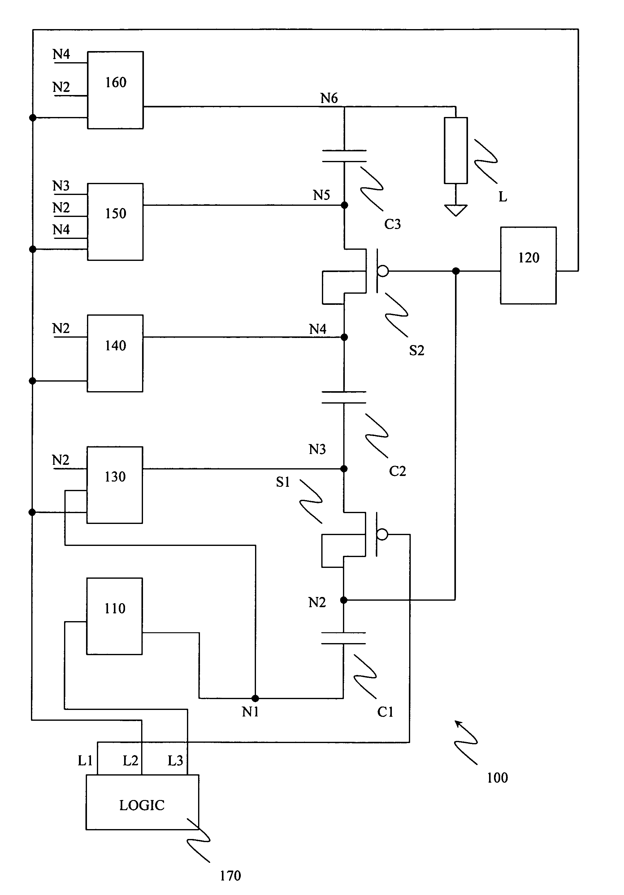
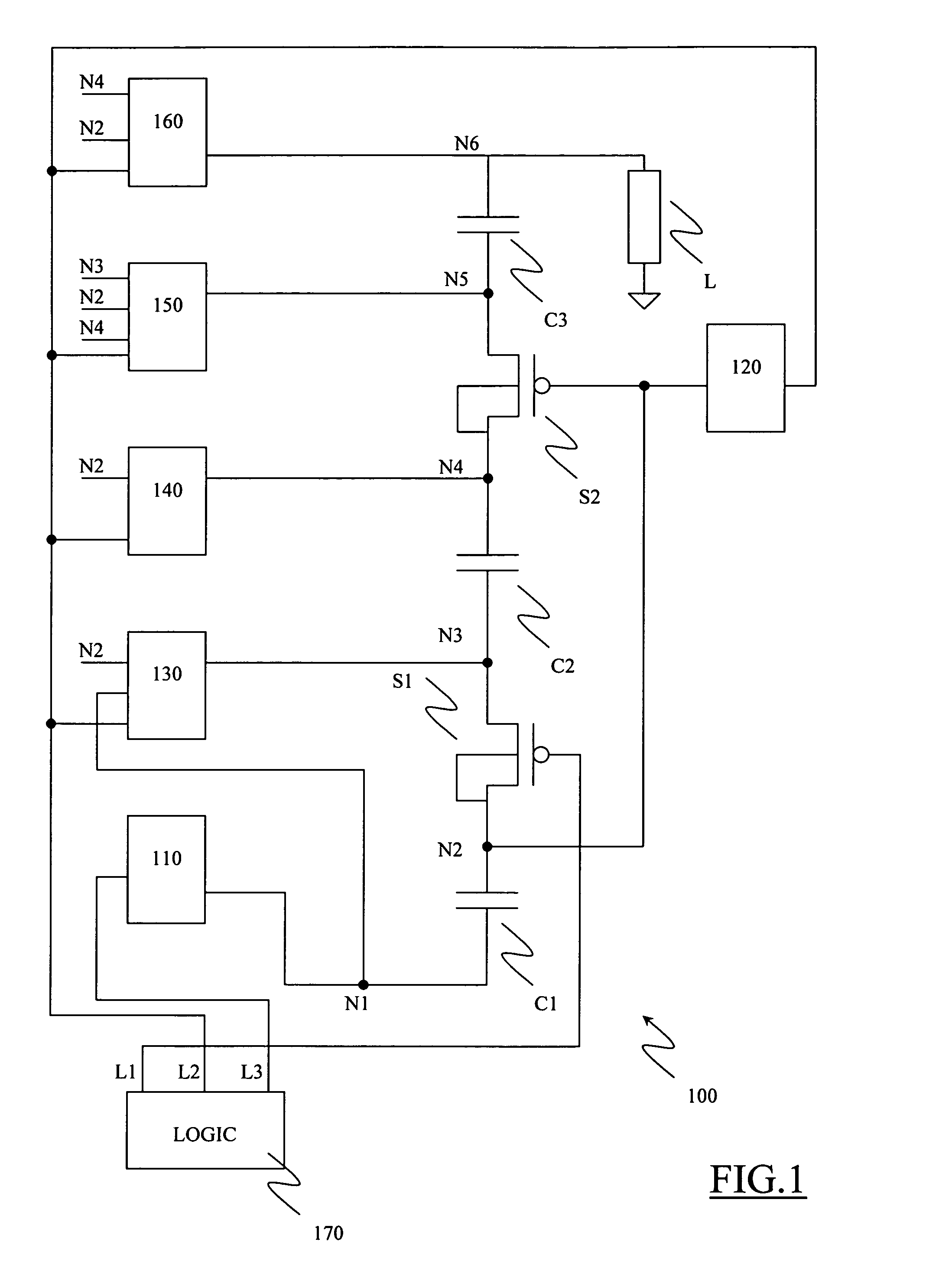
[0031] Referring in particular to FIG. 1, a positive serial charge pump 100 according to an embodiment of the present invention is schematically illustrated. The purpose of the charge pump 100 is to generate positive voltages higher than the IC supply voltage, starting from the latter. More particularly, the charge pump 100 includes a cascade of stages, in the example herein considered three stages. For example, th...


PUM


Abstract

A charge pump circuit includes capacitors and a number of forcing circuits for forcing the voltages on various nodes of the charge pump. The forcing circuits ensure that voltage differences across components thereof are up-limited in absolute value by a predetermined maximum voltage equal to a multiple of the absolute value of the difference between developed forcing voltages and lower than an absolute value of a charge pump voltage. The first and second forcing circuits ensure that the voltage differences across components in the forcing circuits are not higher than the predetermined maximum voltage when at least one among the voltages changes to a voltage higher in absolute value than said predetermined maximum voltage.

Description

[0001] This application claims priority from European patent application Nos. EP05111284.5, filed Nov. 25, 2005, EP06111337.9 filed on Mar. 17, 2006, EP06111477.3 filed on Mar. 21, 2006, EP06112526.6 filed Apr. 12, 2006, EP06113480.5 filed May 4, 2006, EP06119456.9 filed Aug. 24, 2006 and EP06119440.3 filed Aug. 24, 2006 all of which have a common assignee and which are incorporated by reference. CROSS REFERENCE TO RELATED APPLICATIONS [0002] This application is related to U.S. patent application Ser. No. ______, entitled “Non-volatile memory implemented with low-voltages transistors and related system and method” (Attorney Docket No. 2110-225-03), which has a common filing date and assignee and which is incorporated by reference. TECHNICAL FIELD [0003] An embodiment of the present invention relates to the field of the semiconductor Integrated Circuits (ICs), and more particularly, it relates to ICs that have to manage differentiated voltage levels. BACKGROUND [0004] ICs can be clas...

Claims


Application Information

Patent Timeline
IPC IPC(8): G05F1/10
CPCH02M3/07
Inventor CAMPARDO, GIOVANNIMICHELONI, RINO
Owner STMICROELECTRONICS SRL
Why Eureka
Try Eureka