
System control of repeatered optical communications system

Active Publication Date: 2014-09-18
NEPTUNE SUBSEA IP LTD
View PDF5 Cites 7 Cited by
  • Summary
  • Abstract
  • Description
  • Claims
  • Application Information

AI Technical Summary

Benefits of technology

The patent text describes a method to automatically adjust the optical repeater settings to ensure that optical signals traveling in opposite directions are not impacted by the adjustments. This is done by monitoring quality metrics from both terminals and making adjustments accordingly. The adjustments can be made using software, making it easier to optimize optical communication. The technical effect is to improve the efficiency and reliability of optical communication networks.

Problems solved by technology

In some case, the optical repeater adjustments cannot be made without impacting the performance of the optical signals traveling in the opposite direction.

Method used


Image

  • System control of repeatered optical communications system
  • System control of repeatered optical communications system
  • System control of repeatered optical communications system

Examples


Embodiment Construction

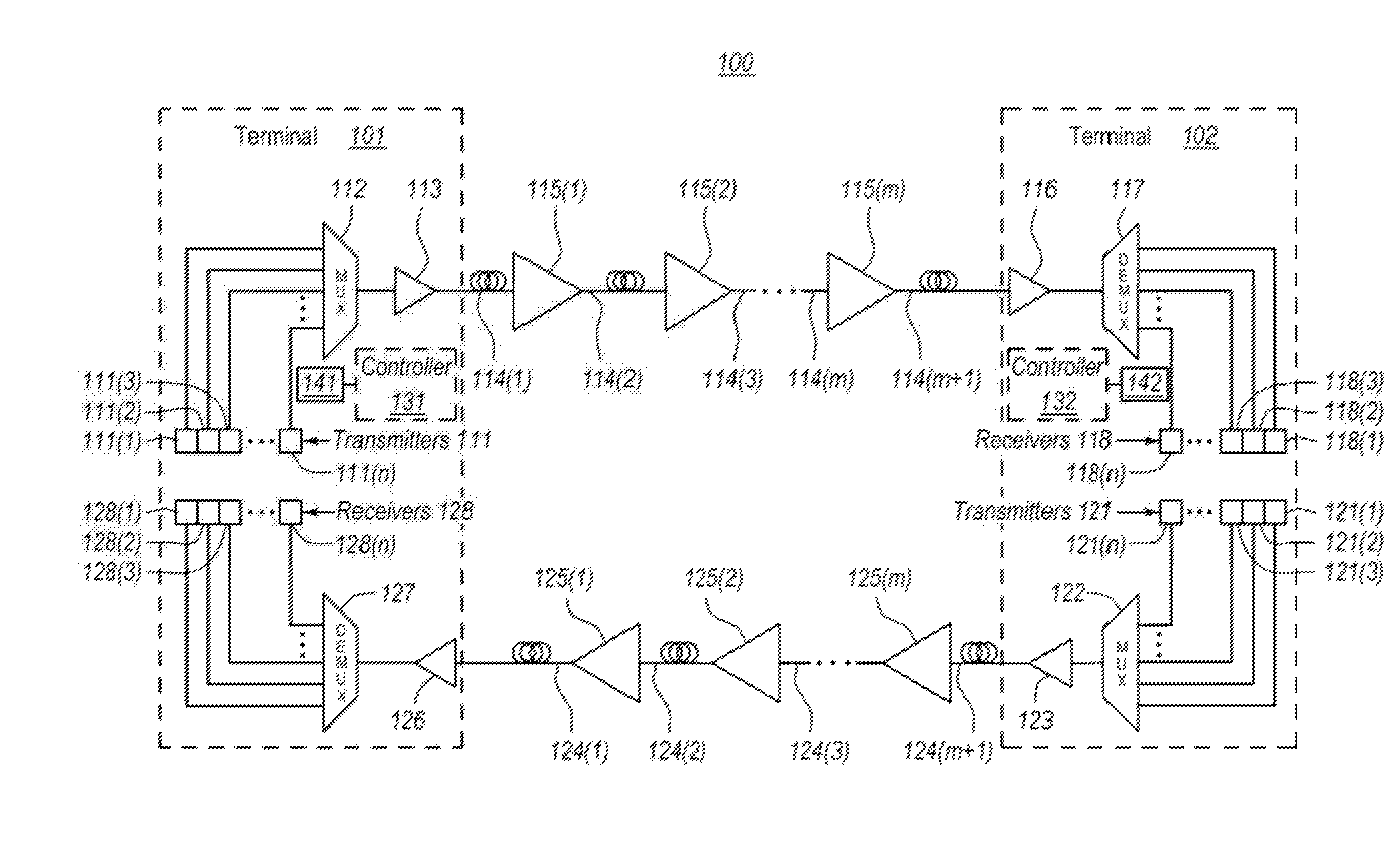
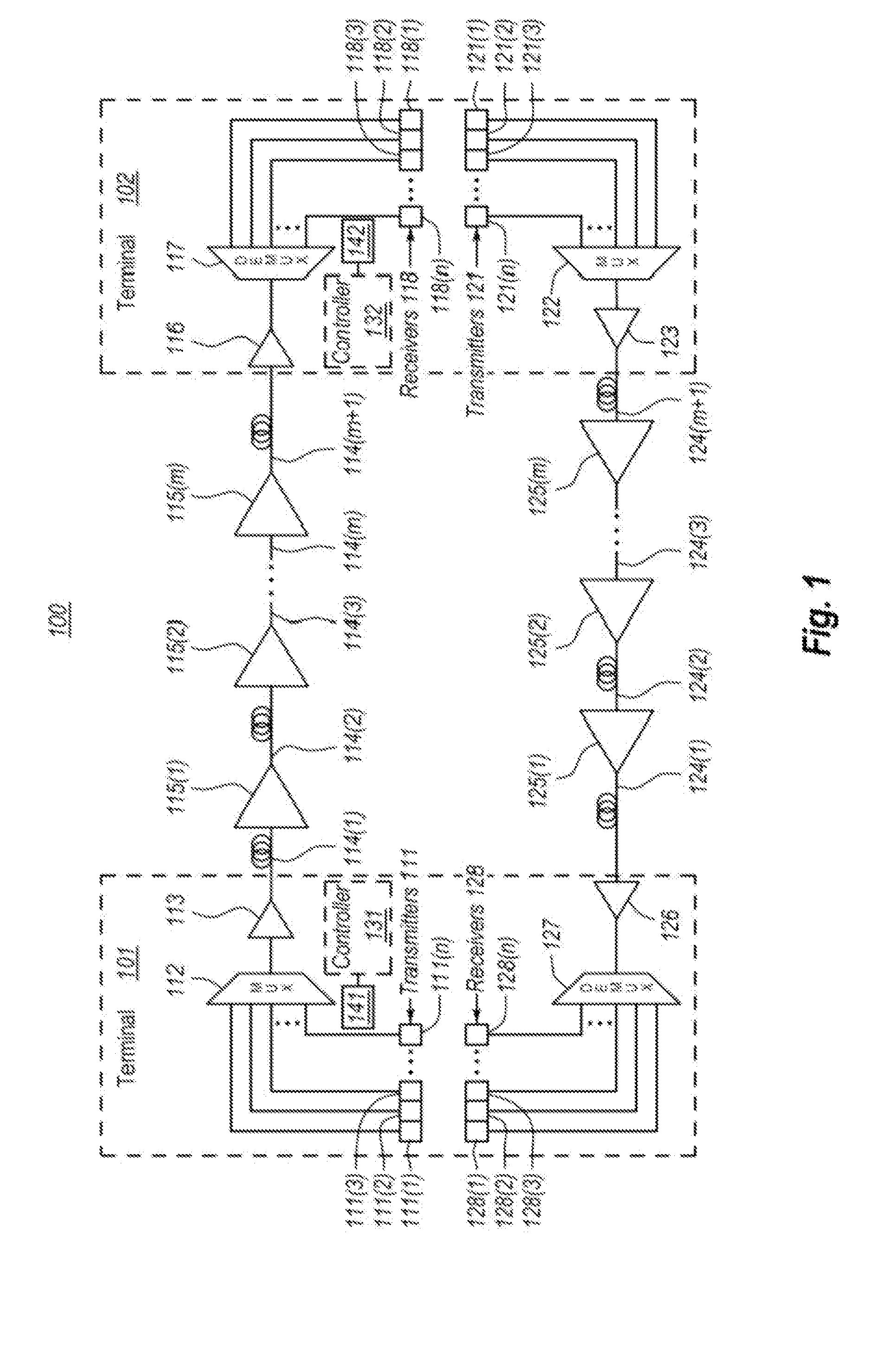
[0013]In accordance with embodiments described herein, the system-level control of a repeatered optical communications system is described. One of the terminals may perform the control by monitoring quality metrics of optical signals received over the communication span. Based on this monitoring, certain adjustments are determined to be performed, and the repeater controllers of the respective optical repeaters are instructed to perform the adjustments. In some case, the optical repeater adjustments cannot be made without impacting the performance of the optical signals traveling in the opposite direction. In that case, the system-level control uses monitored quality metrics from both terminals to determine the adjustments to be made. The system level adjustment may be automated by software or the like thereby making optimization of the optical communications span easier.

[0014]FIG. 1 schematically illustrates an example optical communications system 100 in which the principles descr...


PUM


Abstract

The system-level control of a repeatered optical communications system. In a repeatered optical communications system, two terminals are optically coupled via an optical communications span having one or more repeaters. One of the terminals may perform the control by monitoring quality metrics of optical signals received over the communication span. Based on this monitoring, certain adjustments are determined to be performed, and the repeater controllers of the respective optical repeaters are instructed to perform the adjustments. In some case, the optical repeater adjustments cannot be made without impacting the performance of the optical signals traveling in the opposite direction. In that case, the system-level control uses monitored quality metrics from both terminals to determine the adjustments to be made. The system level adjustment may be automated by software or the like thereby making optimization of the optical communications span easier.

Description

BACKGROUND[0001]Fiber-optic communication networks serve a key demand of the information age by providing high-speed data between network nodes. Fiber-optic communication networks include an aggregation of interconnected fiber-optic links. Simply stated, a fiber-optic link involves an optical signal source that emits information in the form of light into an optical fiber. Due to principles of internal reflection, the optical signal propagates through the optical fiber until it is eventually received into an optical signal receiver. If the fiber-optic link is bi-directional, information may be optically communicated in reverse typically using a separate optical fiber.[0002]Fiber-optic links are used in a wide variety of applications, each requiring different lengths of fiber-optic links. For instance, relatively short fiber-optic links may be used to communicate information between a computer and its proximate peripherals, or between a local video source (such as a DVD or DVR) and a ...

Claims


Application Information

Patent Timeline
IPC IPC(8): H04B10/291H04B10/079H04J14/02
CPCH04B10/2916H04J14/02H04B10/0795H04J14/0227H04B10/0777H04B10/07953H04B2210/074
Inventor VAN LOCHEM, GERHARD WILLEMDESBRUSLAIS, STEPHENWINTERBURN, DAVID
Owner NEPTUNE SUBSEA IP LTD
Learn More