Variable input speed to water pump

Inactive Publication Date: 2005-03-17
BORG WARNER INC
View PDF15 Cites 8 Cited by
  • Summary
  • Abstract
  • Description
  • Claims
  • Application Information

AI Technical Summary

Benefits of technology

[0009] In one preferred embodiment of the present invention, a variable ratio drive belt system is used to drive the water pump. By increasing and decreasing the size of the variable pitch driver and d

Problems solved by technology

This reduction in water pump speed results in a reduction in the coolant flow through the cooling system which can result in poor heater output for the interior of the vehicle when needed in cold weather and also can result in poor coolant flow for engine cooling during hot weather.
Increasing the water pump speed by incr

Method used


Image

  • Variable input speed to water pump
  • Variable input speed to water pump
  • Variable input speed to water pump

Examples


Example

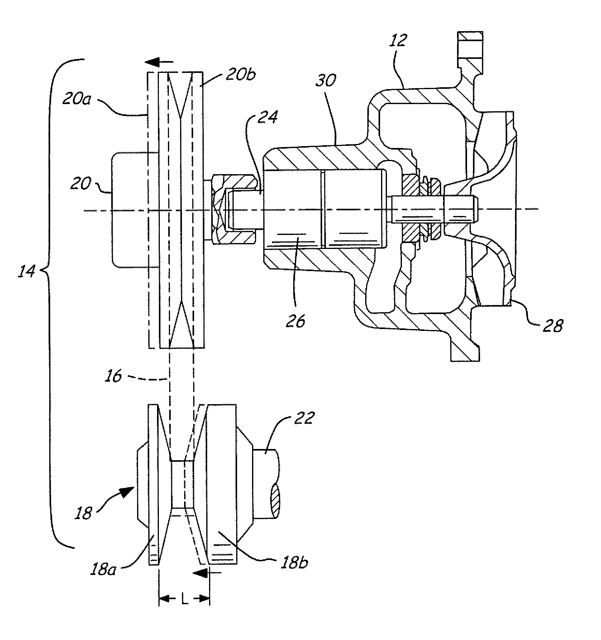
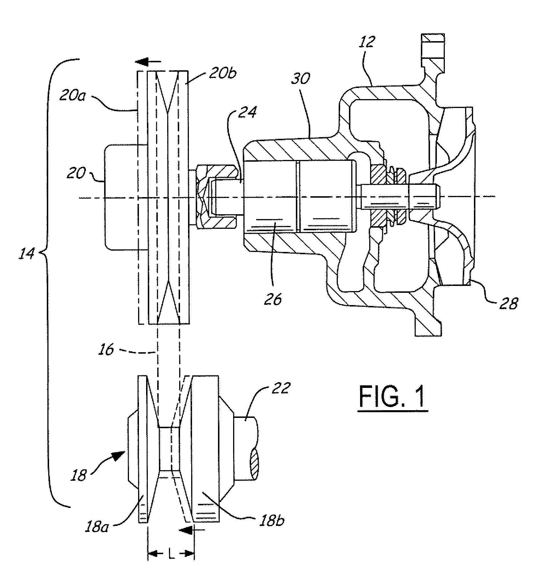
[0017] Referring now to FIG. 1, cooling system 10 having a water pump 12 driven by a variable drive ratio belt system 14 is depicted. The belt system 14 has a drive belt 16 coupled to a variable pitch crankshaft pulley 18, or driver pulley, and a variable pitch water pump pulley 20, or driven pulley.

[0018] To drive the water pump 12, engine speed is rotationally translated to an engine crankshaft 22 from the engine (not shown) in a manner well known in the art. The rotational speed is then transferred from the crankshaft 22 to the variable pitch crankshaft pulley 18. The rotation of the crankshaft pulley 20 causes rotation of the coupled drive belt 16, which in turn causes rotation of the variable pitch water pump pulley 20. The rotation of the variable pitch water pump pulley 20 causes the water pump bearing shaft 24 to rotate, which in turn causes the water pump impellers 28 to rotate, thereby providing engine coolant flow to the engine block in a method well known in the art. Th...


PUM


Abstract

A variable ratio drive belt system is used to drive the water pump. The variable ratio drive belt system comprises a variable pitch water pump pulley, or driven pulley, a variable pitch crankshaft pulley, or driver pulley, and a drive belt that is coupled between a water pump and an engine crankshaft. By increasing and decreasing the size of the variable pitch water pump pulley and increasing the size of the variable pitch crankshaft pulley as a function of engine speed, the water pump speed can be increased at low engine speed to provide improved coolant flow and decreased at higher engine speeds to prevent pump cavitation.

Description

BACKGROUND OF INVENTION [0001] The invention relates generally to water pumps and more specifically to water pumps having a variable speed input. [0002] Water pumps are typically used on vehicles today to provide heat transfer means for an engine during operation. Water pumps are typically driven by the engine crankshaft at a fixed ratio. Thus, as the engine idle speed is reduced, as is the trend in vehicles today to reduce emissions, the water pump speed is correspondingly reduced. This reduction in water pump speed results in a reduction in the coolant flow through the cooling system which can result in poor heater output for the interior of the vehicle when needed in cold weather and also can result in poor coolant flow for engine cooling during hot weather. [0003] Increasing the water pump speed by increasing the drive ratio from the crankshaft will increase the coolant flow at engine idle speeds, but it may result in overspeeding the pump at higher engine speeds which may produ...

Claims


Application Information

Patent Timeline
IPC IPC(8): F04D13/02F04D15/00
CPCF04D15/0066F04D13/021
Inventor SCOTT, GEORGE E.
Owner BORG WARNER INC
Why Eureka
Try Eureka