Method and apparatus for cooling

Active Publication Date: 2008-02-21
AMERICA POWER CONVERSION CORP
View PDF99 Cites 89 Cited by
  • Summary
  • Abstract
  • Description
  • Claims
  • Application Information

AI Technical Summary

Benefits of technology

[0015]Another aspect of the invention is directed to a method of improving the circulation of coolant flowing in a cooling unit configured to have coolant flowing from a condenser to an evaporator, from the evaporator to a compressor, and from the compressor back to the condenser of a cooling unit, with a bypass valve being positioned between the condenser and the evaporator of the cooling unit to divert coolant flowing from the condenser to the evaporator back to the condenser. The method comprises: measuring a parameter of the bypass valve; and manipulating the operation of the bypass valve when the parameter is above a predetermined threshold. In a particular embodiment, the parameter is a position of the bypass valve.
[0016]A further aspect of the invention is directed to a method of controlling air flow over a condenser comprising: measuring a parameter of the condenser; increasing the air flow over the condenser when the measured parameter is above a first predetermined threshold; and decreasing the air flow over the condenser when the measured parameter is below a second predetermined threshold. In one embodiment, the parameter is pressure of coolant flowing from the condenser.
[0017]Yet another aspect of the invention is directed to a method of controlling air flow over an evaporator comprising: measuring a parameter of the evaporator; increasing air flow over the evaporator when the measured parameter is below a first predetermined threshold; and decreasing air flow over the evaporator when the measured parameter is above a second predetermined threshold. In one embodiment, the parameter is pressure of coolant flowing from the evaporator.
[0018]Another aspect of the invention is directed to a method of controlling air flow within a cooling unit having a condenser and an evaporator. In one embodiment, the method comprises: measuring a parameter of coolant flowing from the condenser; increasing the air flow over the condenser when the parameter of coolant is above a first predetermined threshold; decreasing the air flow over the condenser when the parameter of coolant is below a second predetermined threshold; measuring a parameter of coolant flowing from the evaporator; increasing air flow over the evaporator when the parame

Problems solved by technology

Further, with the ever decreasing size of computer equipment, and in particular, computer servers and blades, the number of electrical devices mounted in each rack has been increasing, raising concerns about adequately cooling the equipment.
Heat produced by rack-mounted equipment can have adverse effects on the performance, reliability and useful life of the equipment components.
In particular, rack-mounted equipment, housed within an enclosure, may be vulnerable to heat build-up and hot spots produced within the confines of the enclosure during operation.
A disadvantage of the CRAC-type air conditioning system is that cool air is mixed with the room temperature air, which is inefficient.
For large data cent

Method used


Image

  • Method and apparatus for cooling
  • Method and apparatus for cooling
  • Method and apparatus for cooling

Examples


Example

EXAMPLE

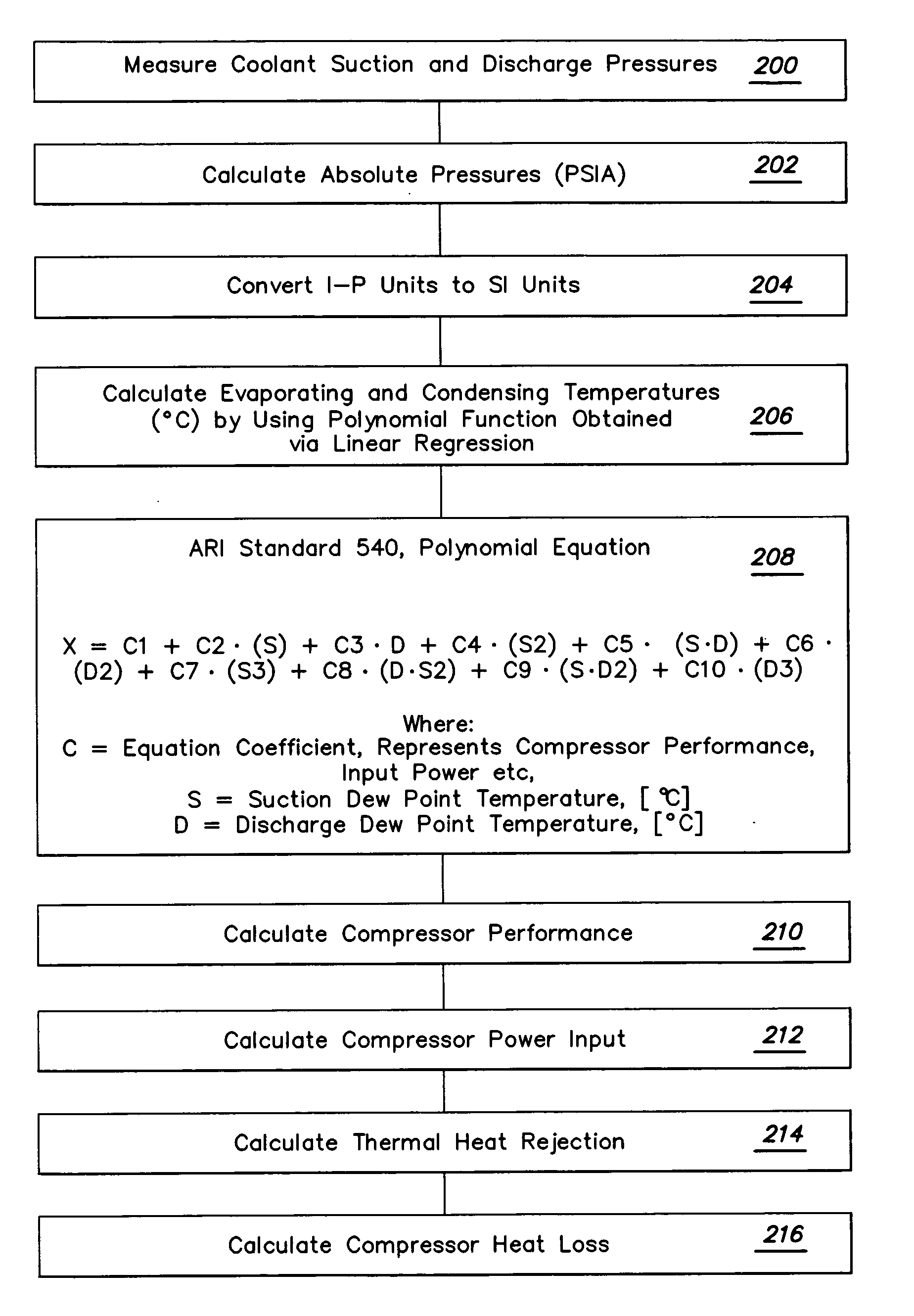
[0120]Using polynomial equation (7), which employs ARI-540 polynomial equation (8), the capacity of a cooling unit may be calculated as follows. Equation (8) is employed, assuming the following coefficients for a cooling unit using a 60 Hz compressor:

Compressor CoolingCoefficientCapacityC12.206E+04C23.403E+02C3−2.265E+02C44.067E+00C5−8.068E−01C61.352E+00C71.309E−02C8−1.900E−02C9−2.813E−03 C10−3.881E−03

[0121]The following estimated values for fan power, condensate production rate and compressor heat loss may be assumed:

[0122]Pf—300 Watts;

[0123]CR—1.6 pounds / hour; and

[0124]Qcomp loss—150 Watts.

[0125]And finally, the following test measurements may be employed for determining the coolant suction and discharge dew point temperatures:

[0126]Evaporating Pressure—136 psig;

[0127]Discharge Pressure—438 psig;

[0128]Suction Dew Point Temperature—47.1° F.; and

[0129]Discharge Dew Point Temperature—123.9° F.

[0130]Based on the foregoing, cooling capacity is calculated as follows:

[0131]Qcomp=6...


PUM


Abstract

A method of calculating sensible cooling capacity of a cooling unit includes obtaining compressor capacity, subtracting compressor heat loss from the compressor capacity, subtracting latent cooling capacity from compressor capacity, and subtracting fan power loss from the compressor capacity. Methods of controlling a cooling unit and embodiments of a cooling unit are further disclosed.

Description

BACKGROUND OF INVENTION[0001]1. Field of Invention[0002]Embodiments of the invention relate generally to devices and methods for cooling a room, such as a data center, equipment room or wiring closet. Specifically, aspects of the present invention relate to data centers containing racks and enclosures used to house data processing, networking and telecommunications equipment, and more particularly to cooling systems and methods used to cool equipment housed by such racks and enclosures.[0003]2. Discussion of Related Art[0004]Over the years, a number of different standards have been developed to enable equipment manufacturers to design rack mountable equipment that can be mounted in standard racks manufactured by different manufacturers. A standard rack typically includes front mounting rails to which multiple units of electronic equipment, such as servers and CPUs, are mounted and stacked vertically within the rack. An exemplary industry standard rack is approximately six to six-and...

Claims


Application Information

Patent Timeline
IPC IPC(8): F25D17/00F25B39/04F25B41/00
CPCF24F11/0086F24F2011/0091F25B49/005F25B49/02Y02B30/743F25B2500/19F25B2600/111F25B2600/112F25B2500/18F24F11/30F24F11/52Y02B30/70F24F11/77F24F11/84
Inventor TUTUNOGLU, OZANLINGREY, DAVID JAMES
Owner AMERICA POWER CONVERSION CORP
Why Eureka
Try Eureka