ECG driven image reconstruction for cardiac imaging

a cardiac imaging and image reconstruction technology, applied in the field of magnetic resonance imaging, can solve the problems of inaccuracy, strong noise, and difficult task of mri technology in cardiac imaging, and achieve the effect of reducing the number of errors and introducing inaccuracy

Inactive Publication Date: 2005-03-17
GE MEDICAL SYST GLOBAL TECH CO LLC
View PDF35 Cites 27 Cited by
  • Summary
  • Abstract
  • Description
  • Claims
  • Application Information

AI Technical Summary

Problems solved by technology

The dynamic nature of a heart, and a desired temporal and spatial resolution for a reliable diagnosis, makes cardiac imaging a challenging task for MRI technology.
In some known MRI imaging systems, the noise is strong enough to introduce inaccuracy in the detection of the peak of the ECG's QRS complex.
The noise may result in the MRI system not identifying the QRS peaks, a false triggering on other parts of the ECG waveform, or time-related inaccuracies, i.e. jitter, in the detection of the QRS peaks.
Therefore an inability to accurately determine the cardiac phase using the QRS complex of the ECG signal can reduce image quality.

Method used


Image

  • ECG driven image reconstruction for cardiac imaging
  • ECG driven image reconstruction for cardiac imaging
  • ECG driven image reconstruction for cardiac imaging

Examples


Embodiment Construction

[0012] As used herein, an element or step recited in the singular and proceeded with the word “a” or “an” should be understood as not excluding plural said elements or steps, unless such exclusion is explicitly recited. Furthermore, references to “one embodiment” of the present invention are not intended to be interpreted as excluding the existence of additional embodiments that also incorporate the recited features.

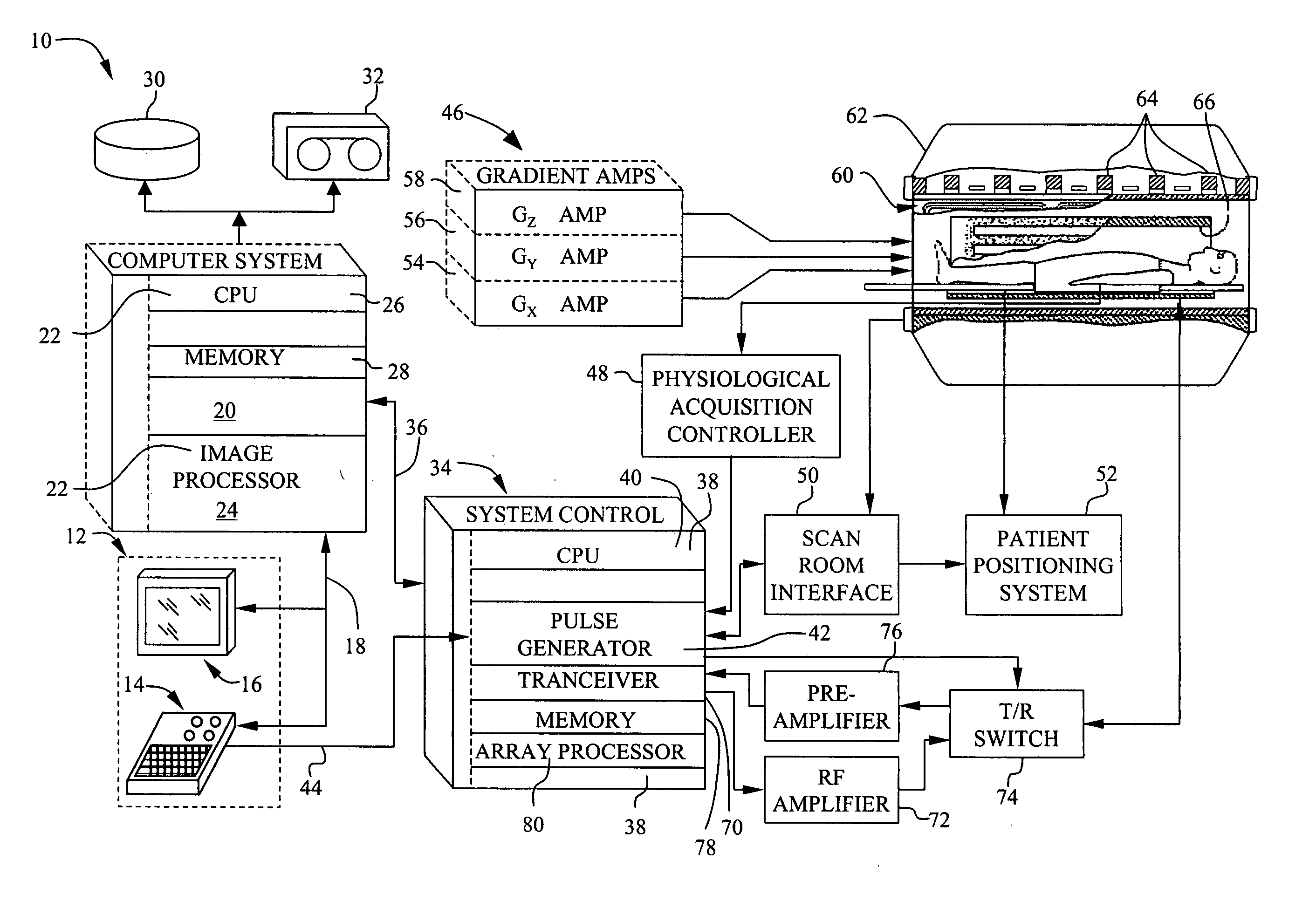
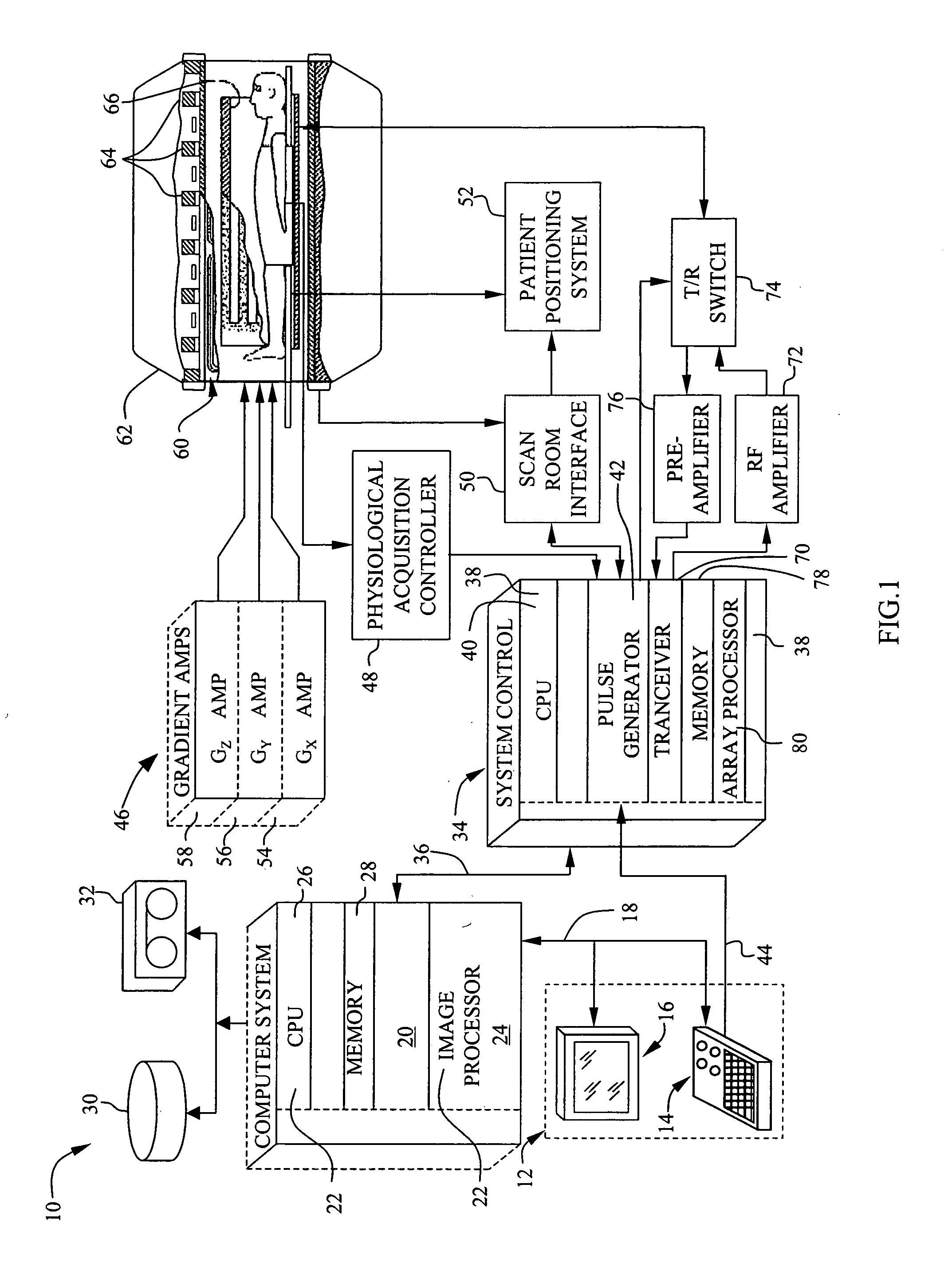
[0013]FIG. 1 is a block diagram of an embodiment of a magnetic resonance imaging (MRI) system 10 in which the herein described systems and methods are implemented. MRI system 10 includes an operator console 12 which includes a keyboard and control panel 14 and a display 16. Operator console 12 communicates through a link 18 with a separate computer system 20 thereby enabling an operator to control the production and display of images on screen 16. Computer system 20 includes a plurality of modules 22 which communicate with each other through a backplane. In the exemplar...


PUM


Abstract

A method for generating an image of a heart at a selected cardiac phase is described. The method includes acquiring a first electrocardiogram (ECG) of the heart at a first phase, introducing a time delay into the first ECG to generate a phase-delayed ECG of the heart at the first phase, and using the first ECG and the phase-delayed ECG to generate an image of the heart.

Description

BACKGROUND OF THE INVENTION [0001] This invention relates generally to magnetic resonance imaging (MRI), and more particularly to cardiac imaging using a MRI system. [0002] The dynamic nature of a heart, and a desired temporal and spatial resolution for a reliable diagnosis, makes cardiac imaging a challenging task for MRI technology. Specifically, as the MRI system is scanning the heart, the heart continues to beat and move, and data is collected at varying cardiac phases. Since the data cannot be acquired instantaneously, so that the cardiac phase of the heart is known for each data set, electrocardiograph (ECG) data is collected to correlate, or ‘tag’, the MRI data with cardiac phase information. The ECG waveform represents the electrical activity of the heart and is correlated into the mechanical motion of the heart. The ECG waveform includes several identification points, P, Q, R, S, and T referred to herein as the QRS complex, which are used to provide cardiac phase informatio...

Claims


Application Information

Patent Timeline
Patent Type & Authority Applications(United States)
IPC IPC(8): A61B5/024A61B5/055A61B5/352G01R33/567
CPCA61B5/02416A61B5/0456G01R33/5673A61B5/7285A61B5/055A61B5/352
Inventor MATHIAS, SANJAY GEORGEKREGER, KEVIN SCOTTVALENT, THOMAS LEO
Owner GE MEDICAL SYST GLOBAL TECH CO LLC
Why Eureka
Try Eureka