X-ray ct apparatus

a computed tomography and x-ray technology, applied in tomography, applications, instruments, etc., can solve the problems of inability to image the whole heart, inhibit high-speed imaging, long subject time constraints, etc., and achieve the effect of reducing subject stress and high image quality

Active Publication Date: 2008-10-16
GE MEDICAL SYST GLOBAL TECH CO LLC
View PDF20 Cites 10 Cited by
  • Summary
  • Abstract
  • Description
  • Claims
  • Application Information

AI Technical Summary

Benefits of technology

[0036]According to the X-ray CT apparatus of the present invention, once an optimal cardiac phase has been set by the optimal cardiac phase setting device and a target position in a subject is defined by the target position defining device, the transport-starting-cardiac-phase calculating device calculates a transport-starting cardiac phase such that the aforementioned target position is scanned at the aforementioned optimal cardiac phase, using a cardiac cycle of the subject, a scan start position in the subject, a transport speed of the imaging table, and an approach-run time for the imaging table, and the scan control device starts transport of the imaging table for a helical scan on the subject when the cardiac phase of the subject coincides with the transport-starting cardiac phase. Therefore, imaging can be made on a region to be imaged in the subject at a high speed and with a low X-ray dose such that a desired portion in the subject, for example, a portion having significant variation due to heartbeats, can be scanned at a desired cardiac phase, for example, at a phase at which the variation due to heartbeats is slowest, and thus, a heart of a subject can be imaged with high image quality while reducing stress on the subject.

Problems solved by technology

In recent years, advances have been made for an X-ray detecting section, such as an increase in the number of detector rows, expansion in the width in a slice direction, and improvement in the gantry rotation speed; however, since the width of the X-ray detecting section in the slice direction still remains shorter than the length of the heart, the whole heart cannot be imaged without shifting the imaged position in an axial or cine scan.
Hence, the aforementioned prospective imaging method generally requires the imaged position to be shifted a plurality of number of times, thus inhibiting high-speed imaging and leading to a long constraining time for the subject.
On the other hand, the retrospective imaging method requires a continuous exposure of the subject to X-rays over a long period of time, resulting in a high exposure dose to the subject.
Especially when such electrocardiographic gating imaging is combined with contrast imaging, the total amount of a contrast agent is increased because of relatively quick flow of the contrast agent injected into the subject, further increasing stress on the subject.
Moreover, when a tomographic image is obtained through multi-segment image reconstruction, discontinuity between projection data segments results in a problem of generation of artifacts in a tomographic image.

Method used


Image

  • X-ray ct apparatus
  • X-ray ct apparatus
  • X-ray ct apparatus

Examples


Embodiment Construction

[0046]Now embodiments of the present invention will be described with reference to the accompanying drawings.

[0047]An X-ray CT apparatus in accordance with one embodiment of the present invention will be described.

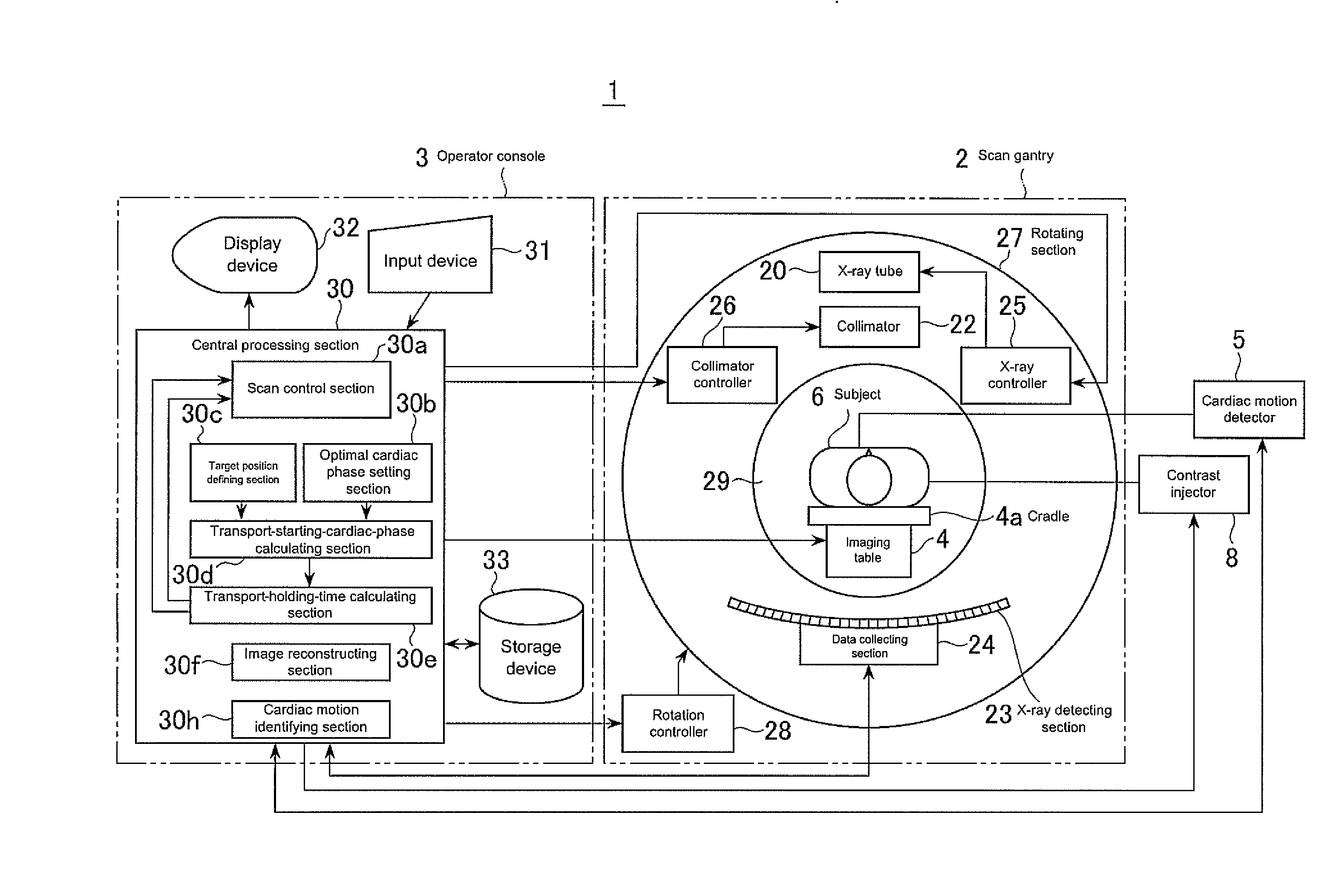
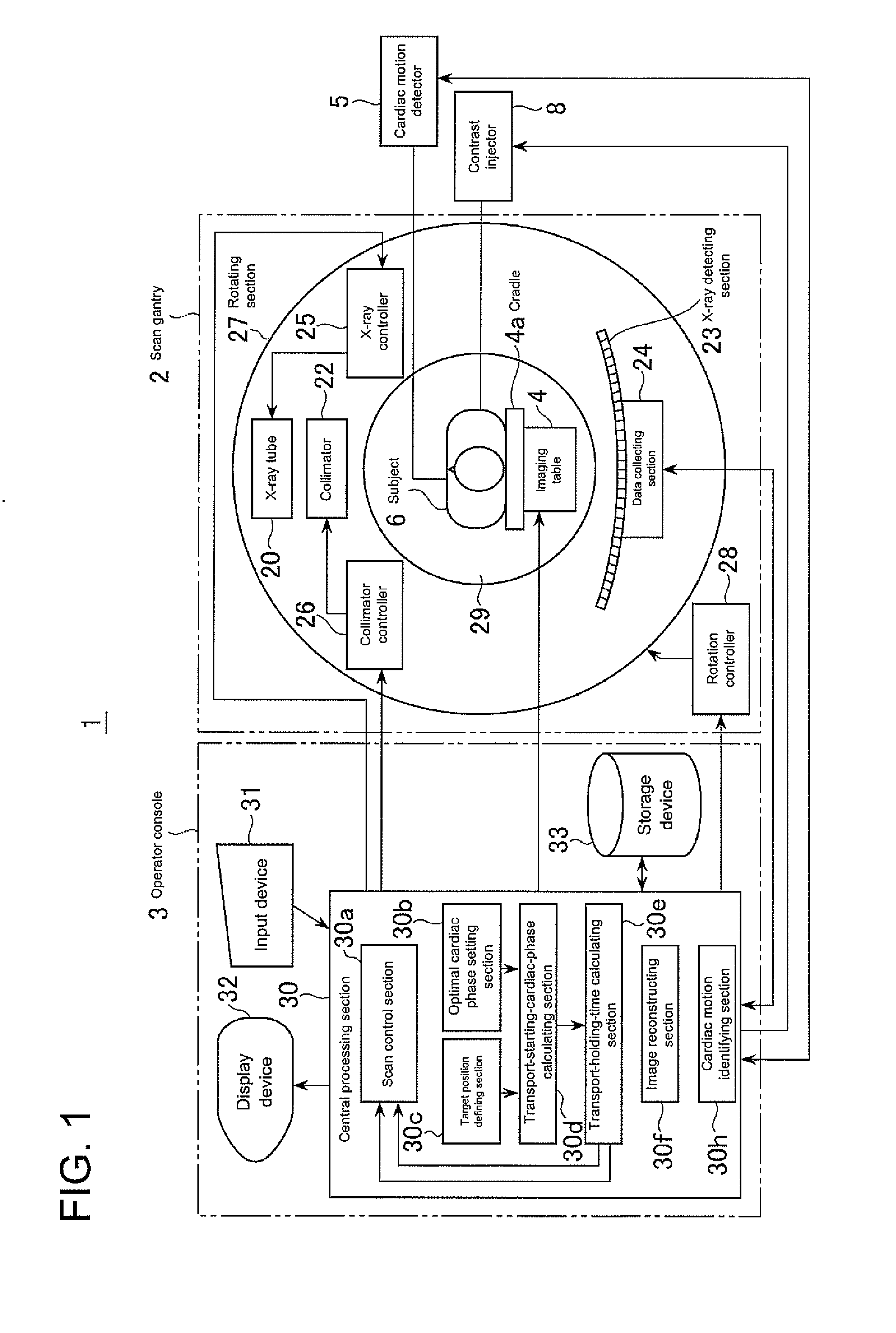
[0048]FIG. 1 is a block diagram showing an overall configuration of an X-ray CT apparatus 1 of the present embodiment. As shown in FIG. 1, the X-ray CT apparatus 1 of the present embodiment comprises a scan gantry 2, an operator console 3, an imaging table 4, a cardiac motion detector 5, and a contrast injector 8.

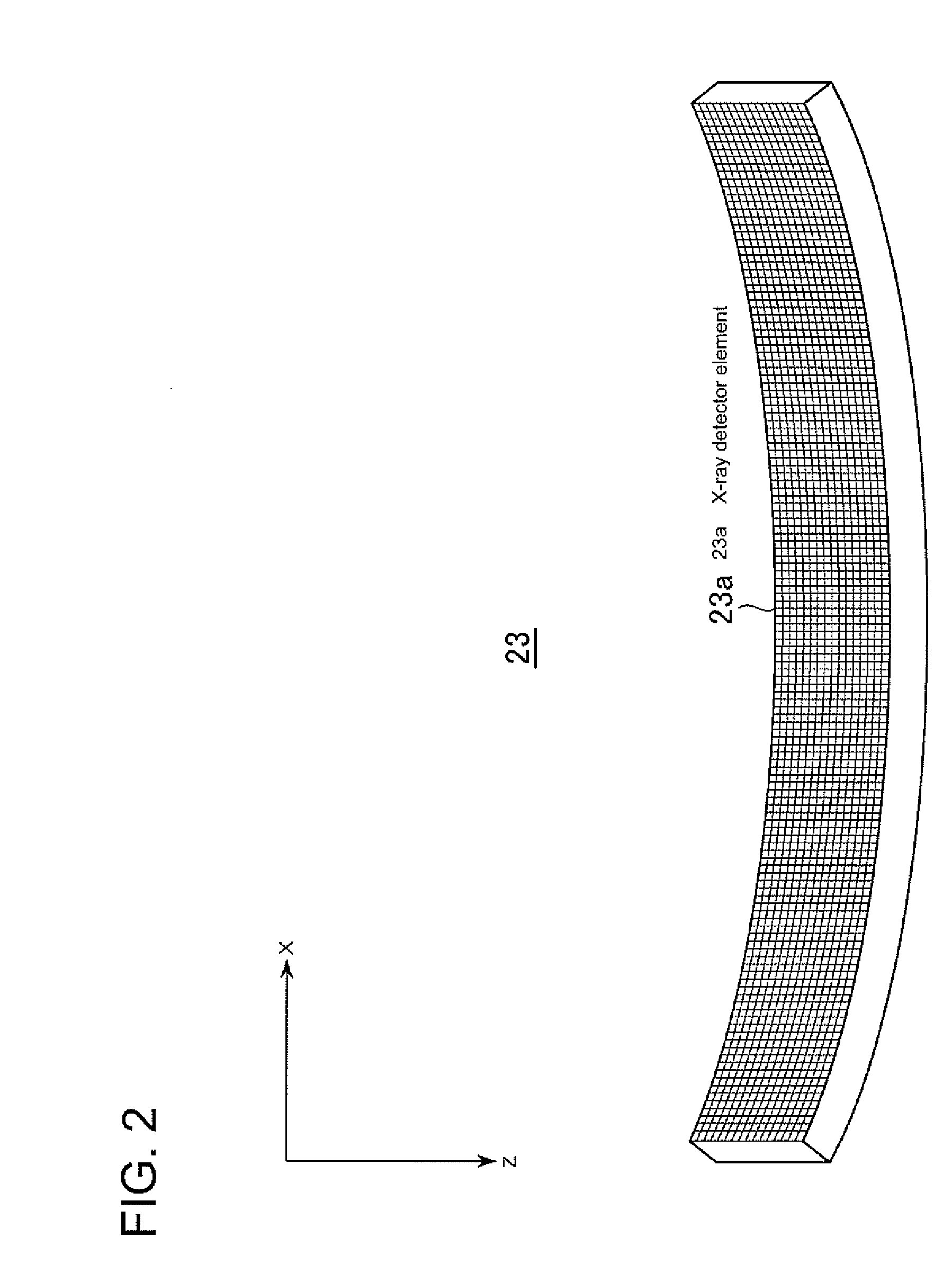
[0049]The scan gantry 2 comprises an X-ray tube 20, a collimator 22, an X-ray detecting section 23, a data collecting section 24, an X-ray controller 25, a collimator controller 26, a rotating section 27, and a rotation controller 28. The scan gantry 2 has therein a bore 29 through which a cradle 4a of the imaging table 4 for placing thereon the subject 6 is transported, and the X-ray tube 20 and X-ray detecting section 23 are disposed to face each other across th...


PUM


Abstract

For the purpose of X-ray CT imaging a heart of a subject with high image quality while reducing stress on the subject, once an optimal cardiac phase has been set by an optimal cardiac phase setting section 30b and a target position in a subject to be scanned when the cardiac phase of the subject is at an optimal cardiac phase is defined at a target position defining section 30c, a transport-starting-cardiac-phase calculating section 30b calculates a transport-starting cardiac phase such that the target position is scanned at the optimal cardiac phase, using the optimal cardiac cycle, target position, scan start position, transport speed of an imaging table, and approach-run time for the imaging table. A scan control section starts transport at the imaging table 4 when the cardiac phase of the subject coincides with the transport-starting cardiac phase, and performs a helical scan with a helical pitch of one or more, for example.

Description

CROSS REFERENCE TO RELATED APPLICATIONS[0001]This application claims the benefit of Japanese Patent Application No. 2007-104825 filed Apr. 12, 2007, which is hereby incorporated by reference in its entirety.BACKGROUND OF THE INVENTION[0002]The subject matter disclosed herein relates to an X-ray CT (Computed Tomography) apparatus for imaging a subject by helical scanning.[0003]Conventionally, X-ray CT imaging on a heart, especially, coronary arteries or the like, of a subject to be imaged involves so-called electrocardiographic gating imaging in which imaging is performed in synchronization with heartbeats.[0004]The electrocardiographic gating imaging includes a prospective imaging method and a retrospective imaging method. The prospective imaging method comprises observing a cardiac cycle averaged based on a plurality of latest heartbeats, and collecting projection data for image reconstruction in synchronization with a cardiac phase at which motion of the heart is considered to be ...

Claims


Application Information

Patent Timeline
Patent Type & Authority Applications(United States)
IPC IPC(8): A61B6/00
CPCA61B5/0402A61B6/032A61B6/541A61B6/027A61B5/318A61B5/33
Inventor IMAI, YASUHIRO
Owner GE MEDICAL SYST GLOBAL TECH CO LLC
Why Eureka
Try Eureka