
Method for co-registering and displaying multiple imaging modalities

Active Publication Date: 2019-01-31
CANON USA
View PDF0 Cites 10 Cited by
  • Summary
  • Abstract
  • Description
  • Claims
  • Application Information

AI Technical Summary

Benefits of technology

This patent describes a way to process images from angiography data using an intravascular imaging catheter. The method can detect the path of the catheter and show it on the image. This allows for better accuracy and can account for any changes in the catheter's location during the imaging process. The method can also use both the directly detected catheter path and the location of radiopaque markers in the angiography data to generate the co-registration path. This approach provides more reliable results and can help with the interpretation of the images.

Problems solved by technology

However, relying only on an intravascular imaging modality such as IVUS or OCT in a PCI procedure is difficult when guiding a catheter to a targeted region such a lesion to gain information about a lumen size, plaque morphology or implanted devices by way of example.
However, detecting an imaging catheter path as the co-registration path is difficult when contrast media fully occupies the targeted region where the intravascular image is acquired.
An issue associated with this is the assumption that the location of the imaging catheter does not change before and during intravascular imaging pullback.
A 3D reconstruction is more processor and time intensive compared to a two-dimensional (2D) reconstruction of the co-registration path.

Method used


Image

  • Method for co-registering and displaying multiple imaging modalities
  • Method for co-registering and displaying multiple imaging modalities
  • Method for co-registering and displaying multiple imaging modalities

Examples


Embodiment Construction

[0033]The following description is of certain illustrative embodiments, although other embodiments may include alternatives, equivalents, and modifications. Additionally, the illustrative embodiments may include several novel features, and a particular feature may not be essential to practice the devices, systems, and methods described herein.

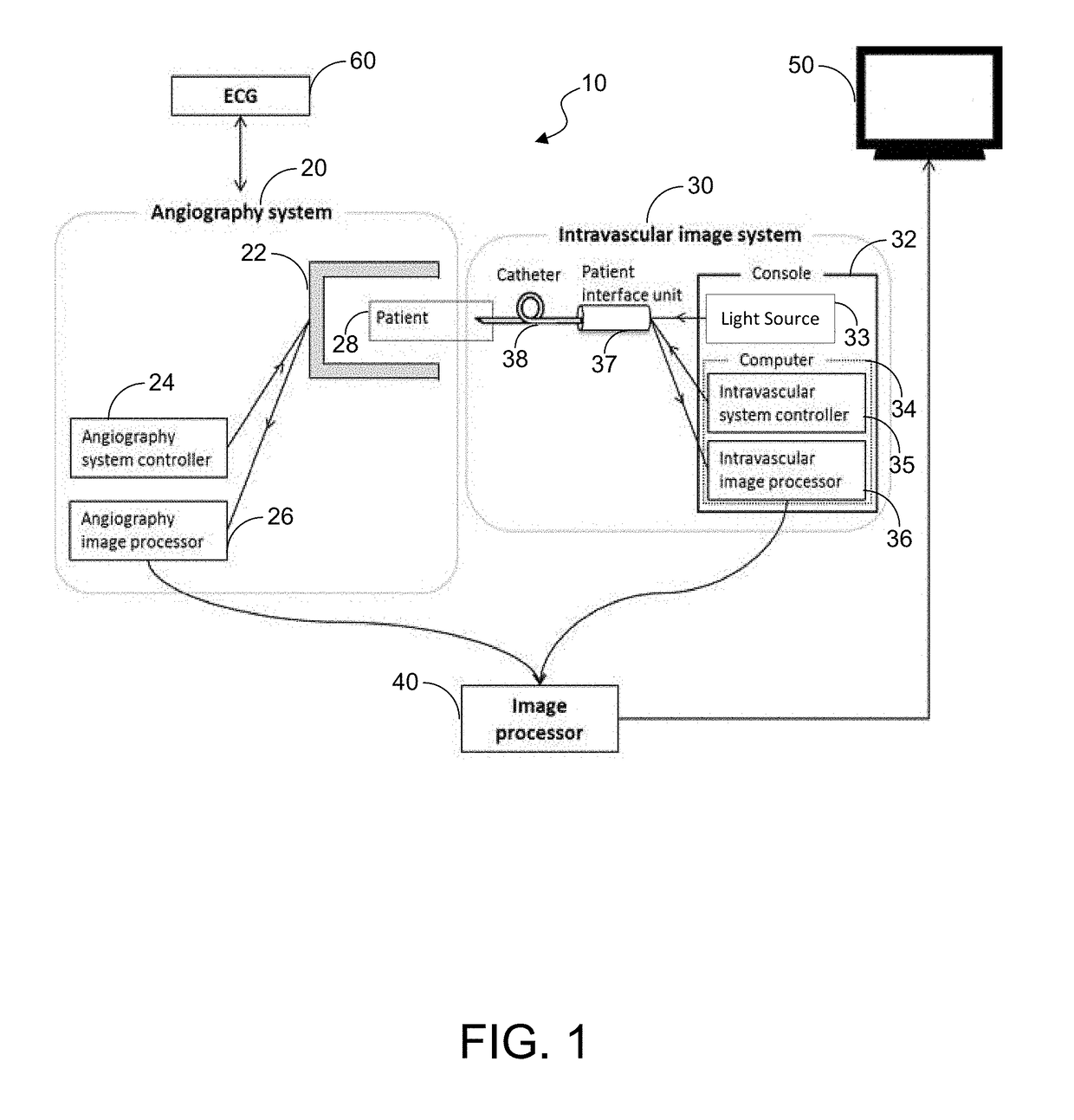
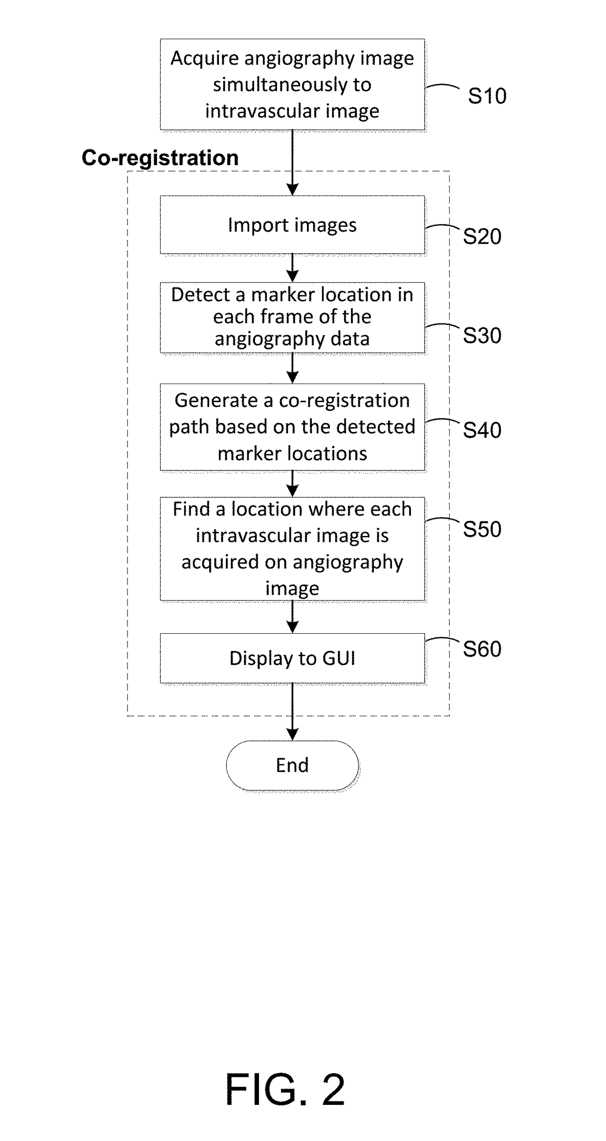
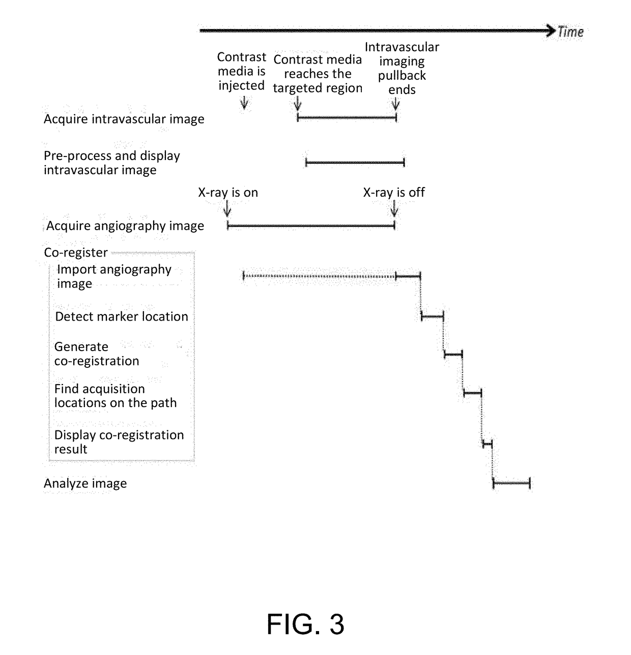
[0034]The present disclosure includes using an angiography image frame that is simultaneously acquired during intravascular imaging pullback and generates an imaging catheter path based on a directly detected location of a radiopaque marker of an imaging catheter. By using the directly detected location, the reliability of co-registration may be calculated. The present disclosure is directed to displaying on a graphical user interface (GUI) an angiography image frame with a co-registration path to show where an intravascular imaging pullback procedure was performed along with an indicator to show the location where the intravascular image frame...


PUM


Abstract

A method for processing angiography image data by using an imaging catheter path that is directly detected from the angiography data as a co-registration path or using detected marker locations from the angiography data to generate a co-registration path. If the acquired angiography data includes synchronized cardiac phase signals and a predetermined quantity of angiography image frames not including contrast media, then a directly detected imaging catheter path is used as the co-registration path. Otherwise the co-registration path is determined based upon detected marker locations from the angiography image data.

Description

CROSS-REFERENCE TO RELATED APPLICATIONS[0001]This application relates, and claims priority, to U.S. Provisional Application Ser. No. 62 / 537,204, filed Jul. 26, 2017, and to U.S. Provisional Application Ser. No. 62 / 680,780, filed Jun. 5, 2018, which applications are hereby incorporated by reference herein in their entireties.BACKGROUNDField of the Disclosure[0002]The present disclosure relates in general to processing angiography image data, and more particularly, to a method that uses an angiography image frame to display the imaging catheter path and calculate the reliability of co-registration between multiple imaging modalities.Description of the Related Art[0003]Coronary angiography imaging and intravascular imaging are important imaging modalities for percutaneous coronary intervention (PCI). A coronary angiography provides longitudinal silhouettes of coronary arteries. The longitudinal silhouettes of the coronary artery are displayed on a monitor to help an interventional card...

Claims


Application Information

Patent Timeline
IPC IPC(8): A61B6/00G06T7/30G06T7/20A61B90/00
CPCA61B6/5211G06T7/30G06T7/20A61B90/39A61B6/504A61B6/4441A61B2090/3966G06T2207/20092G06T2207/30101G06T2207/10116A61B2090/3735A61B2090/3782A61B2090/3614A61B2090/363A61B2090/376G16H50/20A61B5/0035A61B5/0066A61B5/0084A61B5/02007A61B6/00A61B6/12A61B6/481A61B6/486A61B6/487A61B6/503A61B6/5247A61B6/5264A61B8/0891A61B8/12A61B8/5238A61B90/37A61B2090/364G01N2800/323G06T7/0016G06T7/251G06T7/33G06T7/337G06T2200/24G06T2207/10016G06T2207/10101G06T2207/10121G06T2207/10132G06T2207/20044G06T2207/20101G06T2207/30021G06T2207/30172G06T2207/30204G06T2211/404G06V40/14G06V2201/03G06T7/181G06T7/12G06T7/11G06T7/0012G06T2207/10081
Inventor KUNIO, MIE
Owner CANON USA
Learn More