

Binder clip sleeve
a technology of binder clips and sleeve, which is applied in the field of indiciabearing devices, can solve the problems of inconvenient use, unfavorable user safety, and unfavorable document identification and selection, and achieve the effects of convenient use, significant utility, and quick and easy association with the binder clip
- Summary
- Abstract
- Description
- Claims
- Application Information
AI Technical Summary
Benefits of technology
Problems solved by technology
Method used
Image

Examples
Embodiment Construction
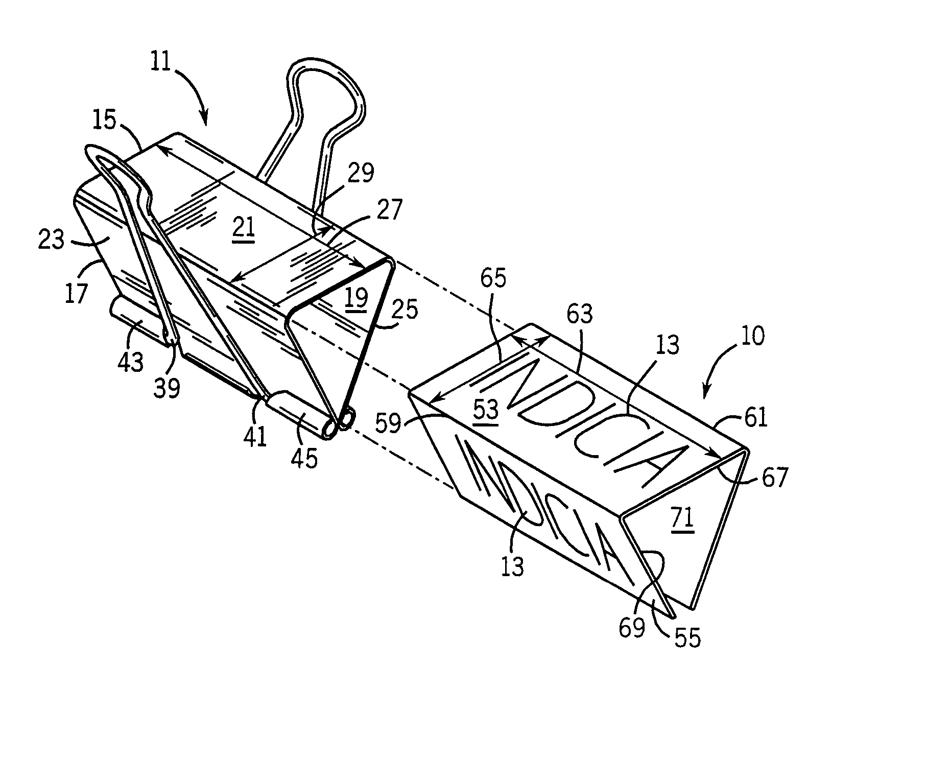
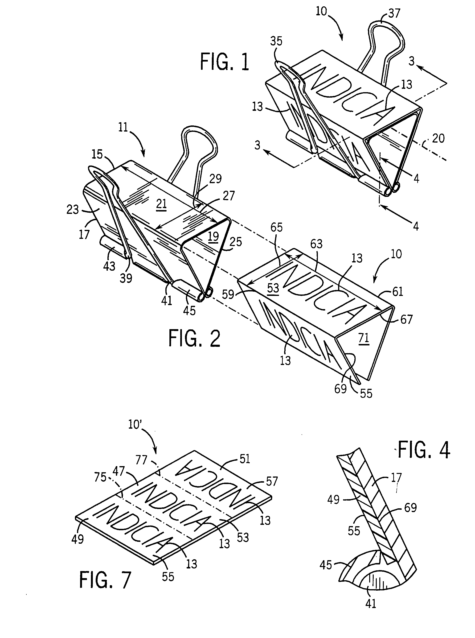
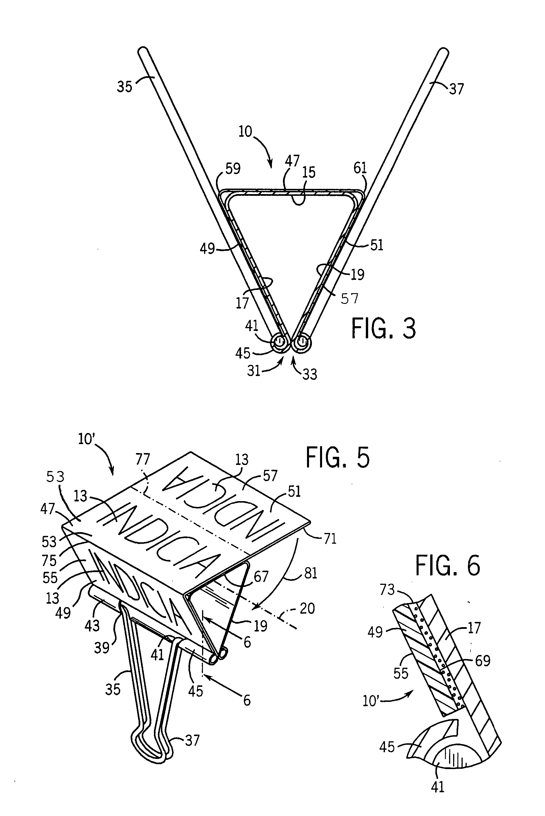
[0033] The binder clip sleeve and the method of use of such binder clip sleeve will now be described in conjunction with binder clip sleeve embodiments 10, 10′ and 10″. Each of binder clip sleeves 10, 10′ and 10″ are provided to secure a wide range of indicia 13 to a binder clip, such as binder clip 11. As will be apparent, the binder clip sleeves 10, 10′ and 10″ share components and features which are the same or similar. For purposes of brevity and simplicity, like reference numbers will be used to describe and identify such components and features.
[0034] An exemplary binder clip 11 will first be described in connection with FIGS. 1 through 6 and 10. The binder clip 11 shown includes a spine 15, first and second resilient jaw portions 17, 19 and axis 20. Spine 15 connects first and second resilient jaw portions 17, 19. The spine 15 and jaw portions 17, 19 preferably have respective outer surfaces 21, 23 and 25 each of which has an area generally defined by respective length and w...
PUM
 Abstract
Description
Claims
Application Information