Adapter frame for a power frame

a technology of adapter frame and power frame, which is applied in the direction of drilling accessories, drilling pipes, drilling casings, etc., can solve the problems of chain getting in the way of other equipment, and achieve the effect of increasing the load capacity of the support frame and increasing the load capacity of the tong support structur

Active Publication Date: 2005-03-24
WEATHERFORD TECH HLDG LLC
View PDF99 Cites 13 Cited by
  • Summary
  • Abstract
  • Description
  • Claims
  • Application Information

AI Technical Summary

Benefits of technology

[0015] In another embodiment, an apparatus for handling a tubular handling device comprises a support frame for supporting the tubular handling device and an adapter frame coupled to the support frame, wherein the adapter frame increases a load capacity of the su

Problems solved by technology

However, the chains may get i

Method used


Image

  • Adapter frame for a power frame
  • Adapter frame for a power frame
  • Adapter frame for a power frame

Examples


Embodiment Construction

[0031] In one embodiment, an adapter frame is provided for use with a power frame to support a tong assembly. When the adapter frame is coupled to the power frame, the load capacity of the power frame is increased, thereby allowing the power frame to be used with larger tongs or tong assemblies such as a riser tong.

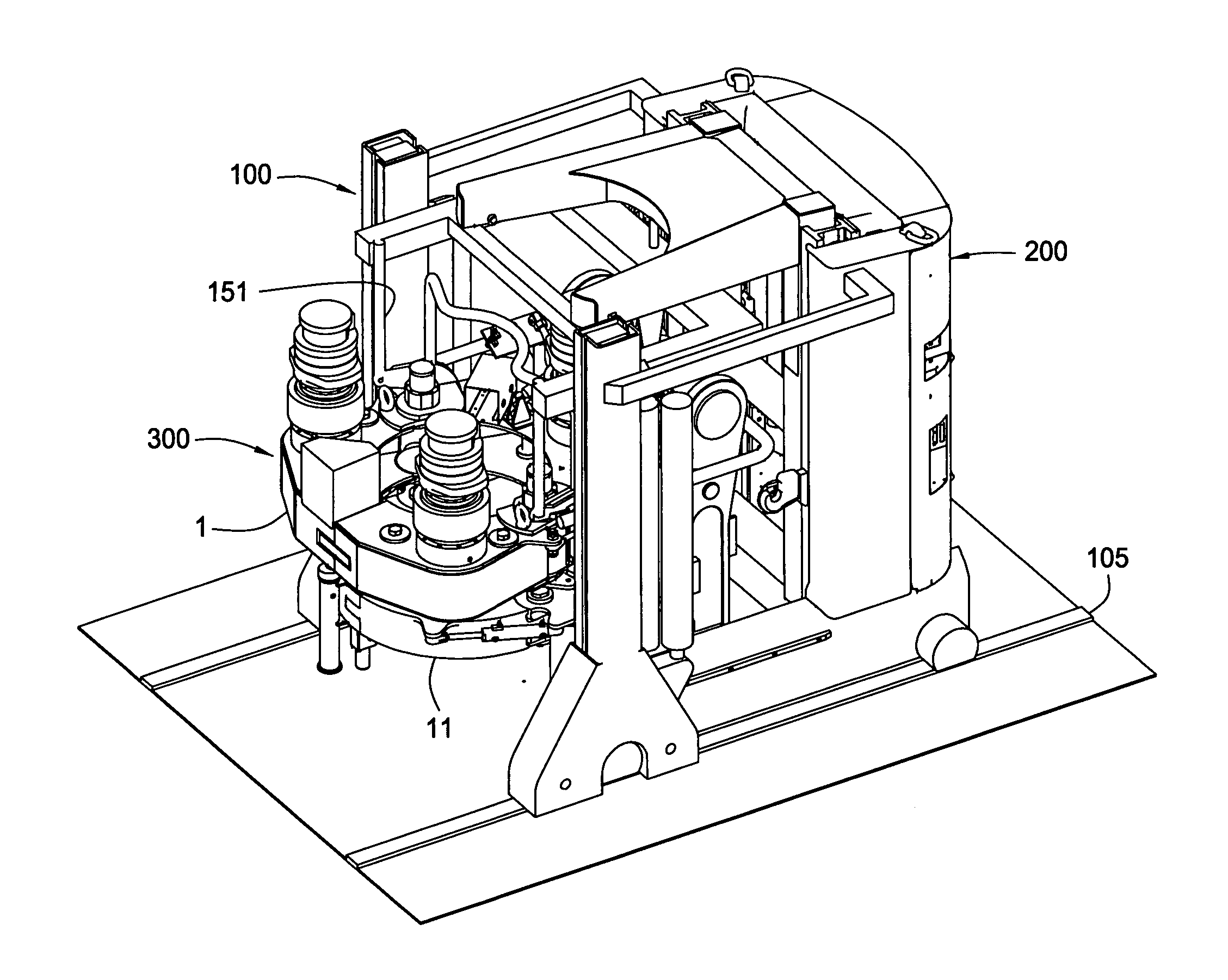
[0032]FIGS. 6-7 show an embodiment of an adapter frame 100. FIGS. 8-9 show the adapter frame 100 coupled to a power frame 200. The coupled frames 100, 200 may be used to support a tong assembly 300 as illustrated in FIGS. 10-13. 1

[0033] Referring to FIG. 6, the adapter frame 100 is shown disposed on a rail system 105. The adapter frame 100 includes a pair of extendable support members 110 disposed on a support base 120. The support base 120 rides on the rail system 105 using one or more wheels. As shown, two wheels are used to move each support base 120. The wheels are connected to the support base 120 using a pin or bolt 125. An opening 130 is formed in the support base...


PUM


Abstract

In one embodiment, an adapter frame is provided for use with a power frame to support a tong assembly. When the adapter frame is coupled to the power frame, the load capacity of the power frame is increased, thereby allowing the power frame to be used with larger tongs or tong assemblies such as a riser tong.

Description

CROSS-REFERENCE TO RELATED APPLICATION [0001] This application claims benefit of co-pending U.S. Provisional Patent Application Ser. No. 60 / 503,822, filed on Sep. 19, 2003, which application is herein incorporated by reference in its entirety.BACKGROUND OF THE INVENTION [0002] 1. Field of the Invention [0003] The present invention generally relates to an apparatus for transporting a tubular handling apparatus. Particularly, the present invention relates an apparatus for reducing a load on a frame for transporting a tubular handling apparatus. More particularly still, the present invention relates to a support frame adapted for use with a power frame for transporting a tubular handling apparatus. [0004] 2. Description of the Related Art [0005] In the construction of oil or gas wells it is usually necessary to construct long drill pipes. Due to the length of these pipes, sections or stands of pipe are progressively added to the pipe string as it is lowered into the well from a drillin...

Claims


Application Information

Patent Timeline
IPC IPC(8): B25B29/00E21B19/16
CPCE21B19/165E21B19/164
Inventor LIESS, MARTIN
Owner WEATHERFORD TECH HLDG LLC
Why Eureka
Try Eureka