Portable axle and tire assembly

a portable axle and tire saddle technology, which is applied in the direction of child seats, transportation and packaging, carriages/perambulators with multiple axes, etc., can solve the problem of limited roof pitch of double-wide manufactured buildings, and achieve the effect of improving the safety aspects of transporting buildings, doubling the braking capacity, and obtaining the capacity

Inactive Publication Date: 2005-03-24
LINDSAY FREDRICK H
View PDF4 Cites 2 Cited by
  • Summary
  • Abstract
  • Description
  • Claims
  • Application Information

AI Technical Summary

Benefits of technology

[0025] A major advantage of the present invention is that each assembly is rated for approximately 6000 lbs. load to about 7000 lbs. load. Assuming a 7000 lb. load capacity, when one is put on the right and one on the left, there is now 14000 lbs. where the axle used today has one 3500 lb. on the left side and one 3500 lb. capacity on the right side for a total of 7000 lbs. The present invention improves the safety aspects of transporting buildings tremendously. For example, with five sets on the right side and five sets on the left side, a total of 70,000 lbs. capacity is obtained. Further, with each assembly having its own braking means, the braking capacity is doubled.
[0026] In addition, by using more tires underneath a manufactured building, the load is more effectively distributed over the highway, thereby reducing the possibility of road damage and the need for more frequent road repair. For example, the state of Minnesota will not allow a building to be transported over its highways with more than six axles. With the present invention, longer and heavier buildings can be transported. Where a larger variety of size buildings can be transported using the present invention, the consequential impact is more jobs in Minnesota.

Problems solved by technology

The roof pitch 18 for double-wide manufactured buildings is limited due to the inherent profile obtained with traditional axle assemblies.

Method used


Image

  • Portable axle and tire assembly
  • Portable axle and tire assembly
  • Portable axle and tire assembly

Examples


Embodiment Construction

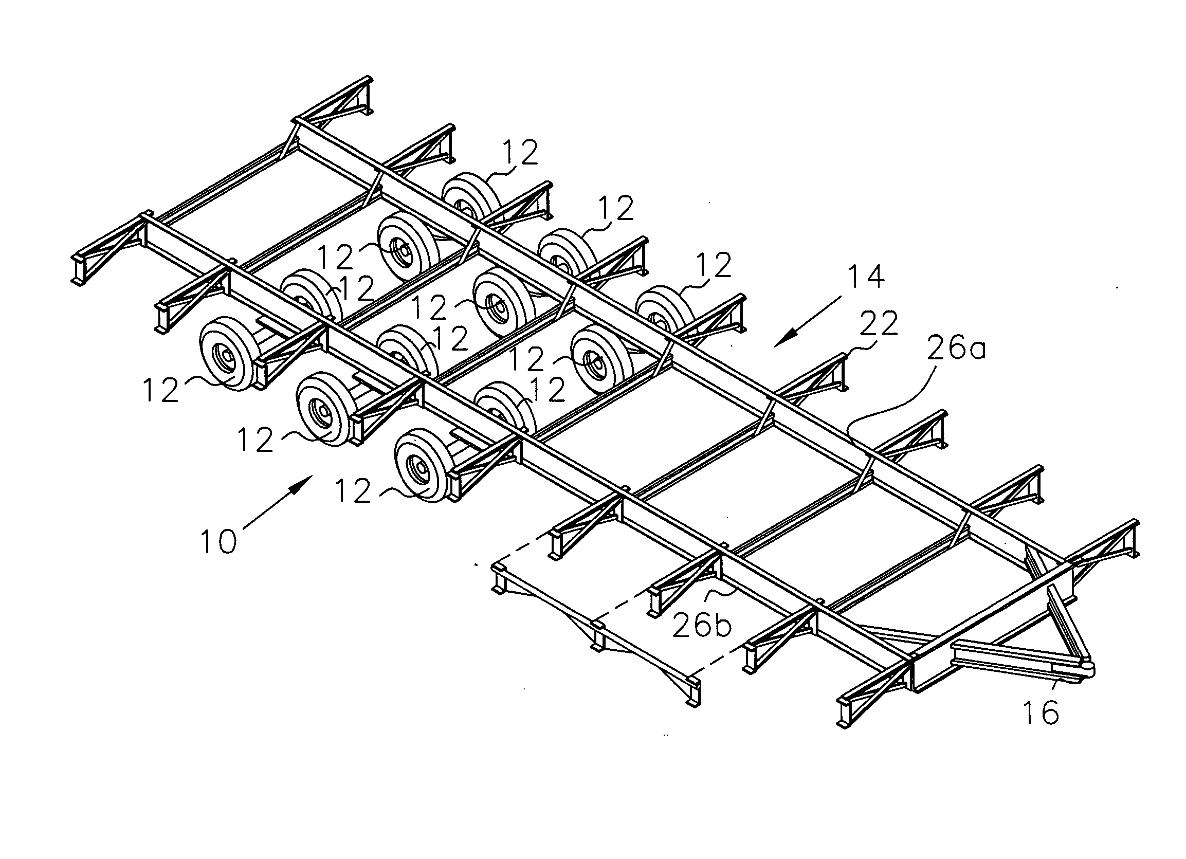
[0038] As depicted in FIG. 3, six portable axle and tire assemblies, as envisioned by the present invention and is generally depicted as 10, are mounted to the two longitudinal I-beams 26a,26b of the frame 14. As can be seen, twelve tires 12 can be used with the present invention. In this case, the frame 14 and outriggers 22,22a of FIG. 2 is depicted. In the embodiment as depicted in FIG. 3, the transverse axle 24, as shown in FIG. 2, is eliminated.

[0039]FIG. 5 is a depiction of the joist system 30 of FIG. 4 incorporating the present invention 10. The present invention 10 fastens each portable axle and tire assembly 10 to each longitudinal I-beam thereby allowing more tires 12 to be installed on a carrier that transports manufactured homes to the building site.

[0040]FIG. 6 is a depiction of a frontal view of the present invention 10, wherein tire rim 34 for mounting tires 12 are located on each side of assembly 10. Each rim 34 is, in turn, mounted to hub extensions 36, which are i...


PUM


Abstract

A method of and assembly for transporting a manufactured building using a portable axle and tire assembly for temporary mounting to each beam of the frame of a transported manufactured building, comprising a pair of rims each mounted to a hub extension, which is in turn attached to yolk. The yolk is attached to an end of an axle. A pair of springs are clamped to said axle. A saddle assembly to which the springs are attached is configured for saddling and receiving the longitudinal beam of the frame of the manufactured building being transported. Each upright member is interconnected with a corresponding longitudinal member. An opposite end of each spring is attached to opposite ends of the longitudinal member. Included are tabs for temporarily attaching the saddle assembly to a flange of the longitudinal beam.

Description

BACKGROUND OF THE INVENTION [0001] 1. Field of the Invention [0002] The invention relates to a reusable portable axle and tire saddle assembly for use in transporting manufactured buildings over the roadways. [0003] 2. Description of Related Art [0004] Transporting manufactured buildings over the highways has been done for years using axle assemblies which are part of the undercarriage frame of the manufactured building. However, savings of $1600 to $2000 may be obtained for each manufactured floor system undercarriage by providing a reusable portable axle and tire assembly. [0005] In addition, current axle assemblies inherently limit the height of a manufactured building, particularly the roof pitch, due to bridge underpass constraints. The saddle configuration of a portable axle and tire assembly, as presented by this invention, will enable a lower profile transportation of the manufactured building thereby allowing roofs to incorporate steeper pitches. Of course, snow load capaci...

Claims


Application Information

Patent Timeline
Patent Type & Authority Applications(United States)
IPC IPC(8): B60G11/04B60G11/23B60G11/42B62D61/10B62D63/06
CPCB60G11/04B60G11/23B60G11/42B60G2200/132B62D63/068B60G2206/0114B60G2300/04B60G2300/40B62D61/10B60G2206/0112
Inventor LINDSAY, FREDRICK H.
Owner LINDSAY FREDRICK H
Why Eureka
Try Eureka