
Inflator

a technology of airbags and inflators, which is applied in the direction of vehicle components, pedestrian/occupant safety arrangements, vehicular safety arrangements, etc., can solve the problems of insufficient protection of passengers and delay in inflating speed of airbags, and achieve the effect of improving operation reliability

Inactive Publication Date: 2005-03-24
DAICEL CHEM IND LTD
View PDF7 Cites 10 Cited by
  • Summary
  • Abstract
  • Description
  • Claims
  • Application Information

AI Technical Summary

Benefits of technology

The present invention provides an inflator with an improved ignition system. The inflator includes a cylindrical housing with a single space inside, which is charged with a pressurized gas and has gas discharge ports at both ends. The housing has a single rupturable plate that breaks when activated by the ignition means, allowing the high-temperature gas to be evenly distributed and discharged from the ports. The interior of the housing is formed in a single space, and the rupturable plates are identical in material, thickness, shape, and area. The inflator uses an ignition means that includes an igniter and a gas generating agent, and the ignition means is integrated with the cylindrical housing. The inflator is compact and easy to assemble.

Problems solved by technology

However, there are the following problems in the inflator disclosed in US 2003 / 0062713 A1:
In such a case, it is considered that the air bag is not developed evenly, a delay of air bag development occurs, resulting that protection of a passenger becomes insufficient, in addition that an inflating speed of the air bag is delayed.

Method used


Image

  • Inflator
  • Inflator
  • Inflator

Examples


first embodiment

[0050] (1) First Embodiment

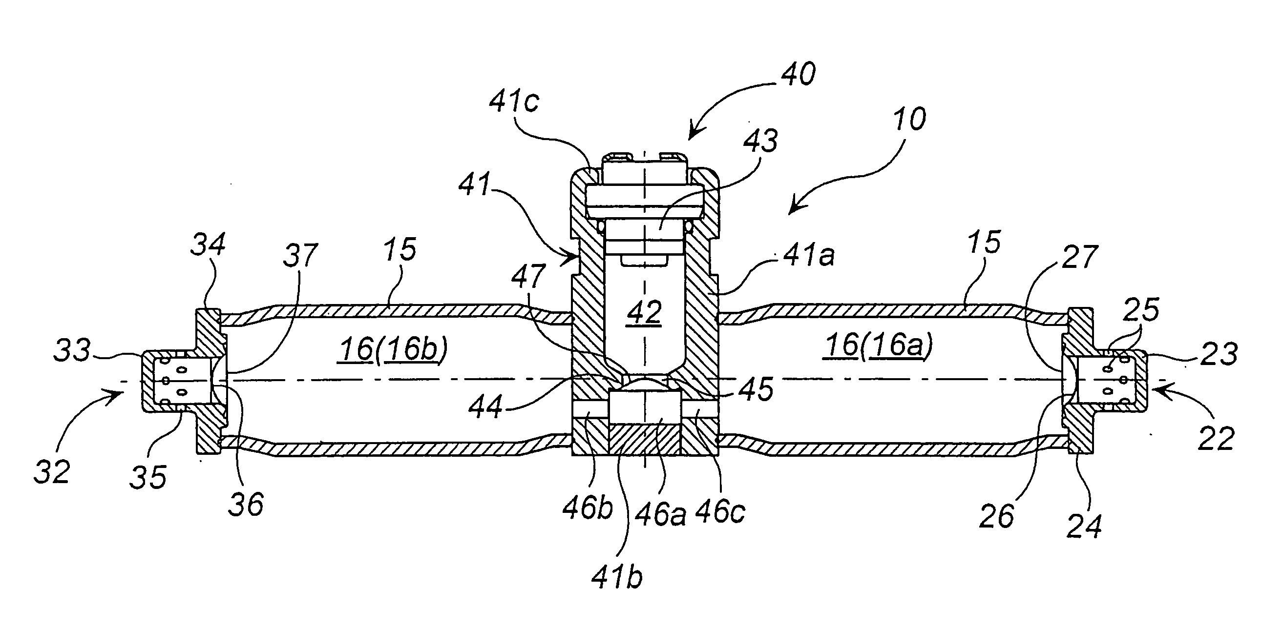
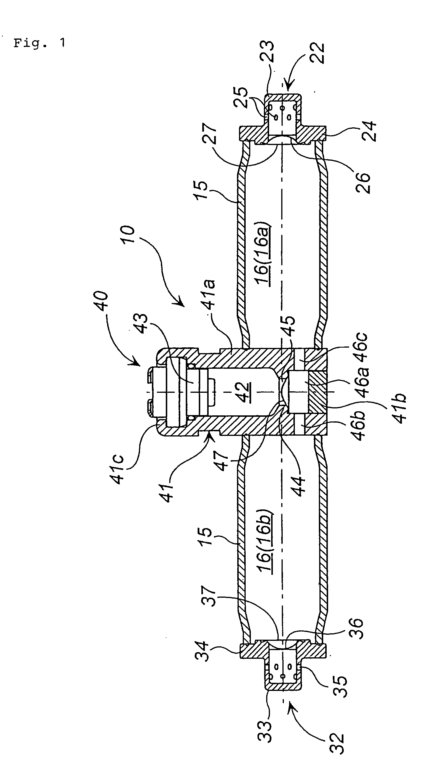
[0051] A first embodiment will be explained with reference to FIG. 1. FIG. 1 is an axial sectional view of an inflator.

[0052] An inflator 10 is provided with a cylindrical housing 15 charged with a pressurized gas and an ignition means 40 for discharging high temperature gas into an interior space 16 (16a, 16b) of the cylindrical housing 15.

[0053] An opening portion at one end of the cylindrical housing 15 is closed by a diffuser cap 22. The diffuser cap 22 comprises a cap portion 23 and a flange portion 24 extending outwardly from an opening portion of the cap portion 23, and a contacting portion between the flange portion 24 and an opening portion of the cylindrical housing 15 is fixed by welding.

[0054] The cap portion 23 of the diffuser cap 22 is provided with a predetermined number of gas discharge holes 25. In order to capture fragments of a second rupturable plate 26, a cylindrical filter made of a wire mesh or the like can be disposed, if require...

second embodiment

[0078] (2) Second Embodiment

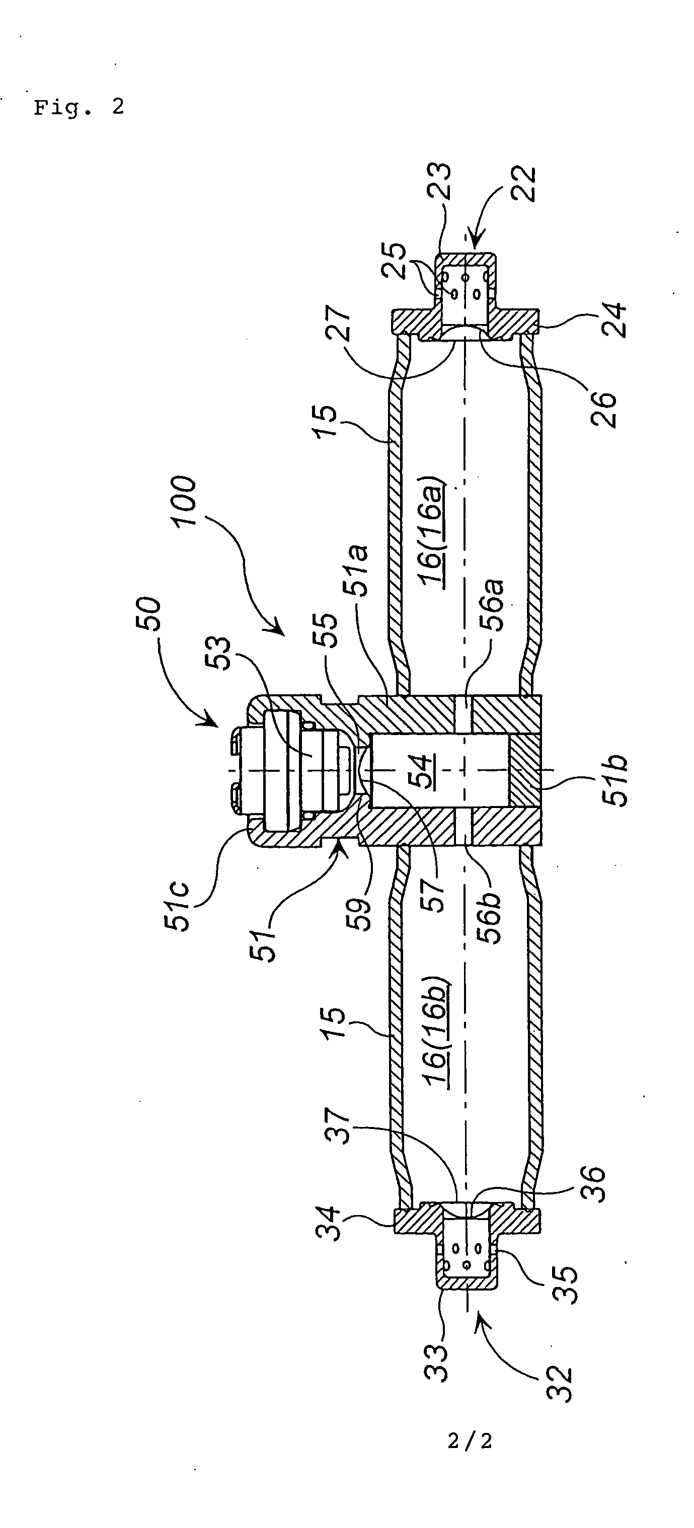
[0079] A second embodiment will be explained with reference to FIG. 2. FIG. 2 is an axial sectional view of an inflator 100.

[0080] Since an inflator 100 has the same structure as the inflator 10 shown in FIG. 1 except for a portion of an ignition means 50, the same portions are denoted by the same numerals and explanation therefore will be omitted.

[0081] In the ignition means 50, an igniter 53 and a gas generating agent (not shown) are accommodated in an ignition means housing 51 (whose interior serves as an ignition means chamber), and it is mounted such that the ignition means housing 51 divides the interior space 16 (16a, 16b) of the cylindrical housing 15 into two portions. The ignition means housing 51 and the cylindrical housing 15 are welded and fixed to each other at a contacting portion therebetween. After the igniter 53 is fitted from an opening portion side of the ignition means housing 51, it is fixed to the ignition means housing by crimpin...


PUM


Abstract

The present invention provides an inflator with high operation reliability. A first rupturable plate 47 is broken by high temperature gas generated from a gas generating agent ignited and burnt by an igniter 43, and the high temperature gas flows into interior spaces 16a, 16b to increase an internal pressure in the interior spaces. As a result, two second rupturable plates 26, 36 are broken by pressurization, so that the pressurized gas is jetted from the gas discharge holes 25, 35.

Description

CROSS REFERENCE TO RELATED APPLICATIONS [0001] This Nonprovisional application claims priority under 35 U.S.C. § 119(e) on U.S. Provisional Application No. 60 / 494,590 filed on Aug. 13, 2003 and under 35 U.S.C. § 119(a) on Patent Application No. 2003-289052 filed in Japan on Aug. 7, 2003; the entire contents of which are hereby incorporated by reference.BACKGROUND OF THE INVENTION [0002] 1. Field of the Invention [0003] The present invention relates to an inflator suitable for an air bag system of an automobile. [0004] 2. Description of Related Art [0005] An inflator used in an air bag system mounted on an automobile is required for reliability of operation thereof. Particularly, in case that an inflator is of a type where an air bag is inflated by discharging a pressurized gas charged with high pressure, it becomes important to break a closing means (a rupturable plate) for allowing discharge of the pressurized gas. As amounting method of the rupturable plate, a breaking method ther...

Claims


Application Information

Patent Timeline
Patent Type & Authority Applications(United States)
IPC IPC(8): B60R21/26B60R21/268B60R21/272
CPCB60R2021/2685B60R21/272
Inventor MATSUDA, NAOKIKATSUDA, NOBUYUKI
Owner DAICEL CHEM IND LTD
Learn More