Dimming adjusting/controlling device of an illuminator

a control device and illuminator technology, applied in lighting devices, instruments, light sources, etc., can solve the problems of sudden change of illumination, uncertainty or even fear, and the eyes of people can be hardly immediately adapted to sudden illumination changes, so as to avoid the danger of sudden shutoff of the environmental illuminator and avoid the effect of sudden extinction of the illuminator

Inactive Publication Date: 2005-03-24
LU JOHN
View PDF5 Cites 12 Cited by
  • Summary
  • Abstract
  • Description
  • Claims
  • Application Information

AI Technical Summary

Benefits of technology

[0004] It is therefore a primary object of the present invention to provide a dimming adjusting / controlling device of an illuminator. By means of the dimming adjusting / controlling device, the illuminator can be gradually weakened from a bright state to a shimmery or totally extinguished state. Therefore, the uncertainty caused by sudden extinction of the illuminator can be avoided. Also, the danger caused by sudden shutoff of the environmental illuminator can be avoided.

Problems solved by technology

It is known that human eyes can be hardly immediately adapted to suddenly changed illumination.
Therefore, in the case that an illuminator of the environment is suddenly extinguished or dimmed, people will temporarily feel totally dark.
This often leads to uncertainty or even fear.
In the case that the sudden darkness takes place just before sleeping, some people often become emotionally unstable or even fail to fall asleep.
However, the wall light or table light will still emit light with a fixed brightness which may be too strong or too weak.
In the case that the brightness of the light emitted from the wall light or table light is too weak, in the instant of turning off the main light, a user will still feel sudden darkness.

Method used


Image

  • Dimming adjusting/controlling device of an illuminator
  • Dimming adjusting/controlling device of an illuminator
  • Dimming adjusting/controlling device of an illuminator

Examples


Embodiment Construction

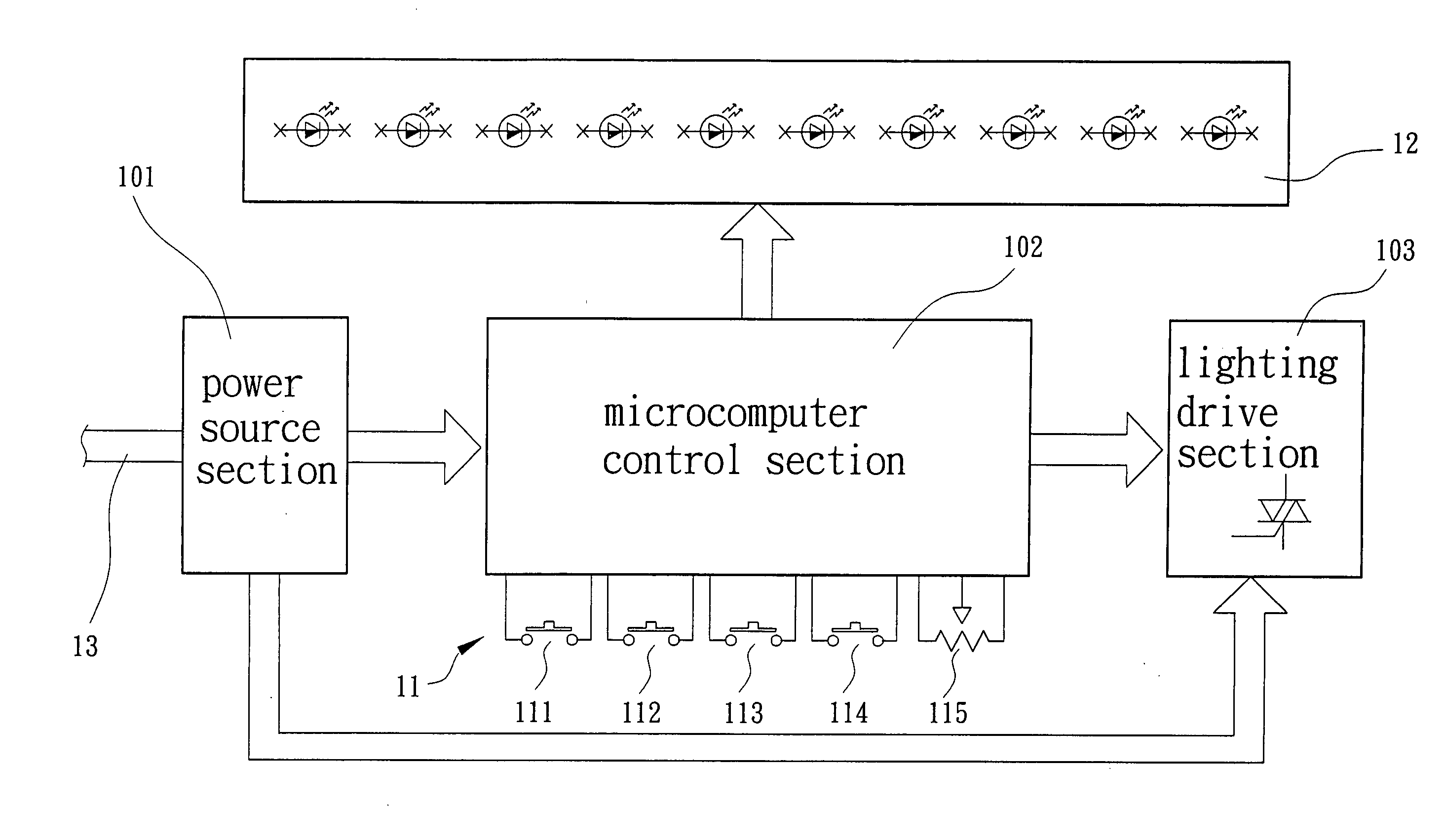
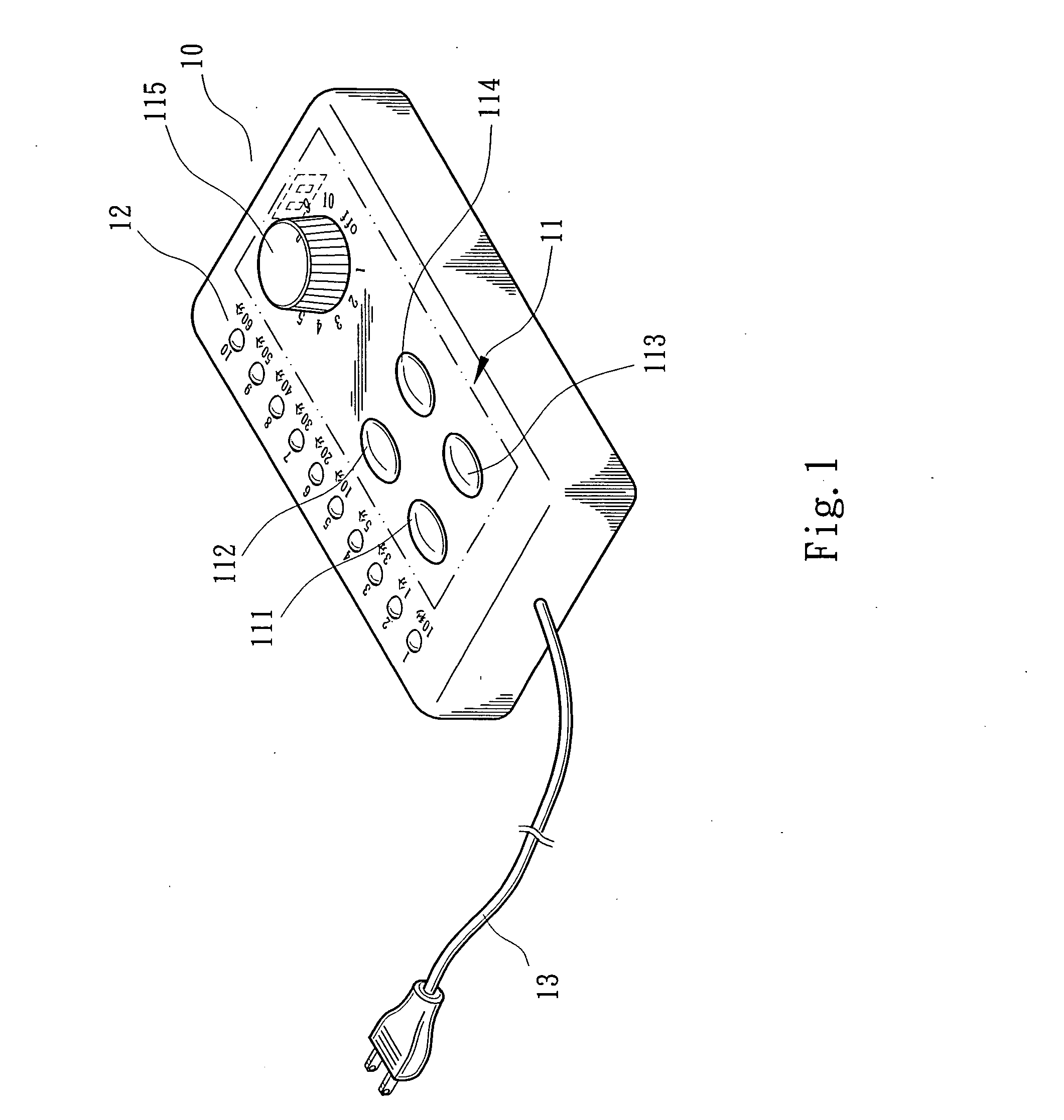
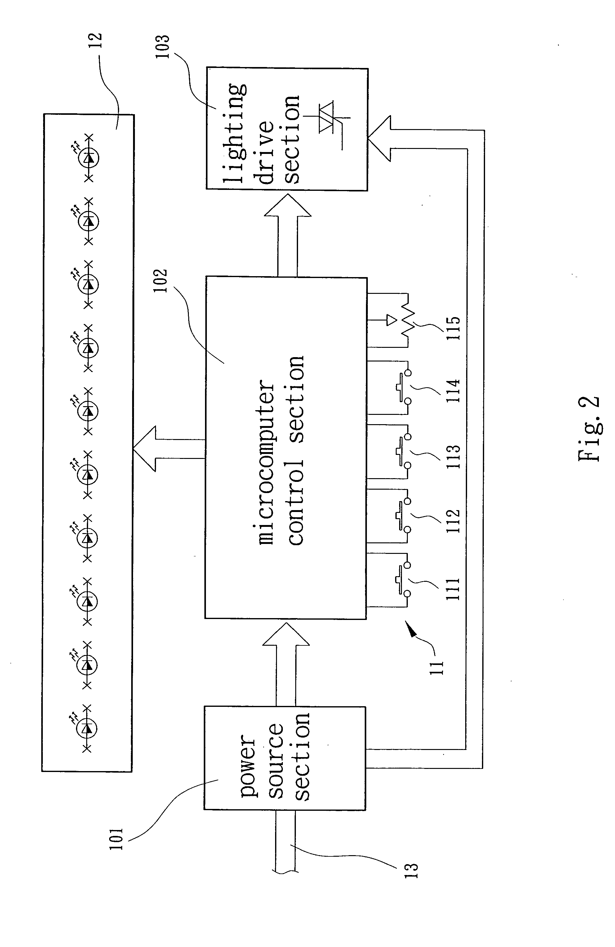
[0013] Please refer to FIG. 1. The present invention includes a housing 10 and multiple function keys 11 and indicator lamps 12 arranged on outer side of the housing 10. A power cable 13 extends from the housing 10 for connecting with a power source. In the housing 10 are disposed a power source section 101, a microcomputer control section 102 and a lighting drive section 103 as shown in FIG. 2. The power cable 13 is directly connected to the power source section 101 which provides power to the microcomputer control section 102 and the lighting drive section 103. The microcomputer control section 102 includes an activating switch 111, a strengthening button 112, weakening button 113, automatic weakening button 114 and shimmer adjustment button 115.

[0014] Referring to FIG. 3, according to a first embodiment of the present invention, housing 10 is connected with an external main light 20. The power cable 13 is plugged into a socket. The power source section 101 provides power for the...


PUM


Abstract

A dimming adjusting / controlling device of an illuminator, including a power source section, a microcomputer control section and a lighting drive section. The microcomputer control section includes multiple function keys and indicator lamps for adjustment and indication. The adjusting / controlling device is connected with the illuminator. By means of setting and activating of the function keys, the microcomputer control section sends out signals to the lighting drive section, whereby the illuminator is automatically gradually weakened from a bright state to a shimmery or totally extinguished state. Moreover, by means of the function keys, the brightness and modulation sequence and time period of the illuminator can be controlled.

Description

BACKGROUND OF THE INVENTION [0001] The present invention is related to a dimming adjusting / controlling device of an illuminator. The dimming adjusting / controlling device can adjust the brightness as desired. Especially after the power is cut off, the illuminator can still emit light for a set time. Then the illuminator is automatically gradually weakened to a shimmery state. Therefore, the change of the illumination is smoothened so that a user can easily adapt his / her eyes to the environment. Accordingly, those adults or children afraid of sudden darkness will no more feel uncomfortable in the instant of turning off the illuminator. [0002] It is known that human eyes can be hardly immediately adapted to suddenly changed illumination. Therefore, in the case that an illuminator of the environment is suddenly extinguished or dimmed, people will temporarily feel totally dark. This often leads to uncertainty or even fear. In the case that the sudden darkness takes place just before slee...

Claims


Application Information

Patent Timeline
Patent Type & Authority Applications(United States)
IPC IPC(8): H05B37/02H05B39/08
CPCH05B37/0281Y02B20/42H05B39/083H05B47/16Y02B20/40
Inventor LU, JOHN
Owner LU JOHN
Why Eureka
Try Eureka