
Triggered vacuum gap that controllably sustains a vacuum arc through current zeros

a vacuum arc and current zero technology, applied in the direction of spark gap circuits, overvoltage arrestors using spark gaps, high-tension/heavy-dress switches, etc., can solve the problems of increasing the load on the network, affecting the operation of the substation, so as to prevent premature interruption of the closing operation and prevent premature extinction of the vacuum arc. , the effect of facilitating the operation

Pending Publication Date: 2022-03-31
S&C ELECTRIC
View PDF0 Cites 0 Cited by
  • Summary
  • Abstract
  • Description
  • Claims
  • Application Information

AI Technical Summary

Benefits of technology

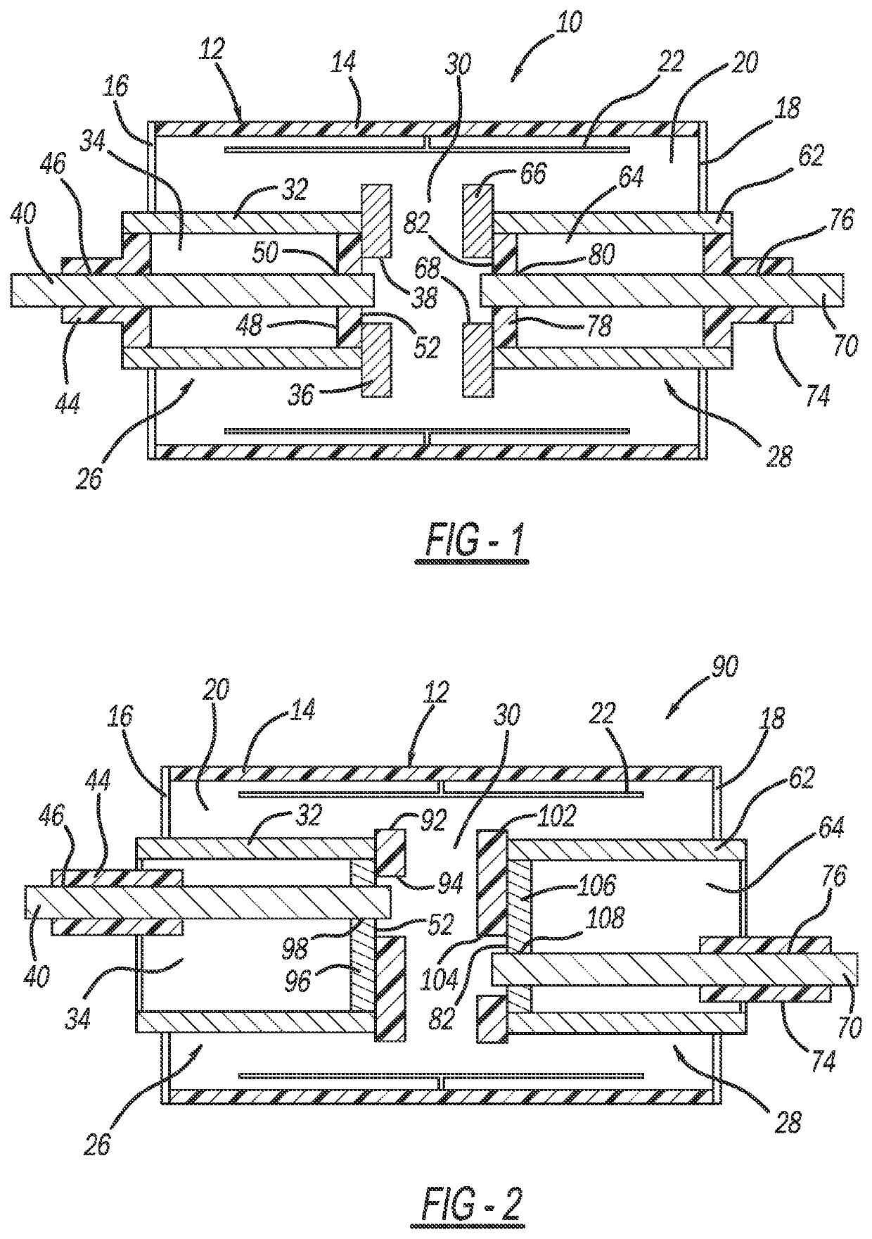
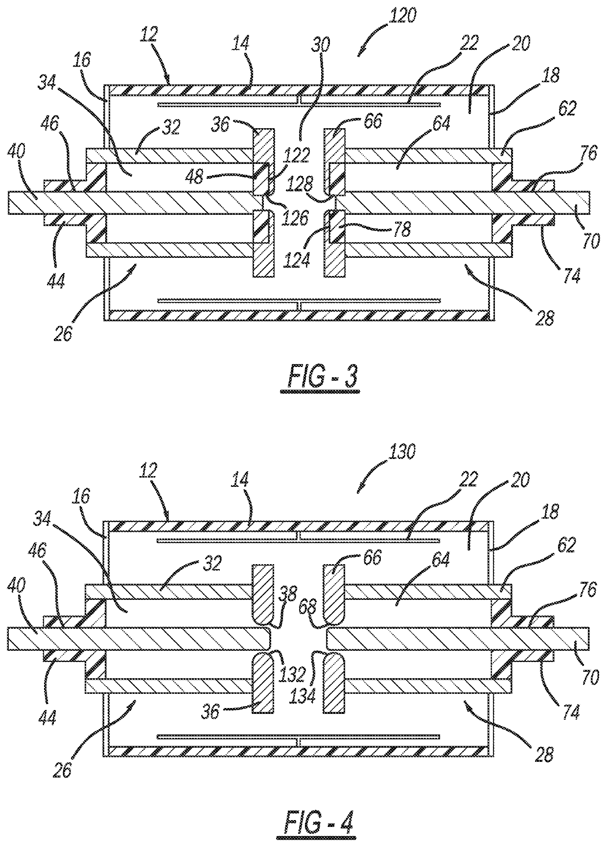
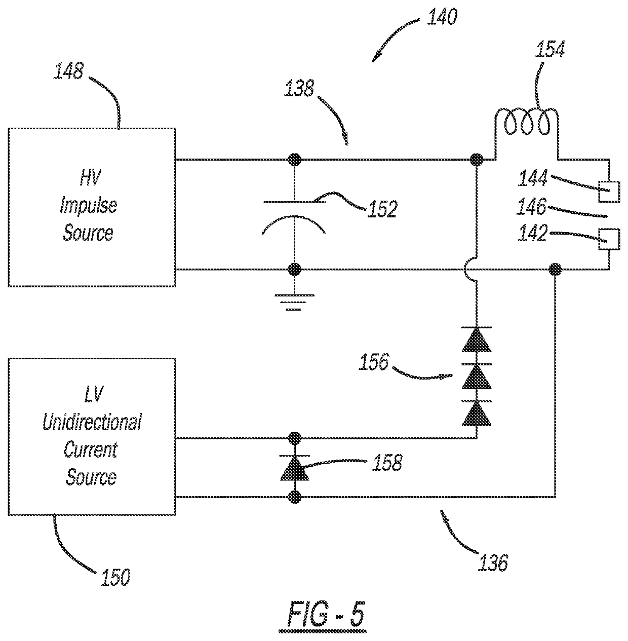
The patent describes a triggered vacuum gap (TVG) device that can be used as a closing switch in power systems. The device has two main electrodes and a first triggering electrode with a gap between them. A high voltage impulse is applied to break down the gap and create plasma to sustain a vacuum arc in the main gap, preventing premature extinction of the arc. The device can also have a second triggering electrode for use in cases where the main gap voltage polarity requires it. TheTVG device helps ensure successful synchronized closing and provides a prolonged duration of unidirectional current for maintaining the vacuum arc. The triggering circuit ensures the device operates efficiently and provides a reliable closing switch for power systems.

Problems solved by technology

Periodically, faults occur in the distribution network as a result of various things, such as animals touching the lines, lightning strikes, tree branches falling on the lines, vehicle collisions with utility poles, etc.
Faults may create a short-circuit that increases the load on the network, which may cause the current flow from the substation to significantly increase, for example, many times above the normal current, along the fault path.
This amount of current causes the electrical lines to significantly heat up and possibly melt, and also could cause mechanical damage to various components in the substation and in the network.
However, the switching devices required to generate these short pulse durations are relatively complicated and expensive.
These are powerful features, but those features have generally only been used in pulse power applications and not in electric power systems for synchronized closing applications.
Those transient high frequency currents are attenuated very quickly and most often they are not even noticed when closing is performed by mechanical switches, but for TVG devices they might have a catastrophic effect.
There is a high probability that a TVG device will interrupt current in one of several high frequency current zeroes that occur in the first 100 microseconds after current was initiated in the TVG device.
That is, however, a very important issue for TVG devices used for closing operations in power systems, because if arc control is not adequate there could be melting of the main electrodes and molten drops and particles can shorten out the triggering gap.

Method used


Image

  • Triggered vacuum gap that controllably sustains a vacuum arc through current zeros
  • Triggered vacuum gap that controllably sustains a vacuum arc through current zeros
  • Triggered vacuum gap that controllably sustains a vacuum arc through current zeros

Examples


Embodiment Construction

[0022]The following discussion of the embodiments of the disclosure directed to a TVG device including a triggering circuit for applying voltage across a triggering gap between a main electrode and a triggering electrode, where the triggering circuit includes a high voltage impulse source and a low voltage unidirectional current source, is merely exemplary in nature, and is in no way intended to limit the disclosure or its applications or uses.

[0023]This disclosure proposes a TVG device including two triggering electrodes, where one is provided in the vicinity of each main electrode and voltage is applied across and current into each triggering gap by a separate triggering circuit for a prolonged duration after breakdown of the TVG main gap, i.e., current supplied into the triggering gap by the triggering circuit is controlling conduction of the TVG device main gap and should be present as long as TVG device conduction is desired. This disclosure also proposes a process for causing ...


PUM


Abstract

A triggered vacuum gap (TVG) device that has application as a closing switch for synchronized closing in distribution and transmission power systems. The TVG device controllably sustains a current arc in the device through initial current zeros created by power system transients and, thereby, prevents premature interruption of the closing operation. The TVG device includes main electrodes defining a vacuum gap therebetween and a triggering electrode providing a triggering gap between one main electrode and the triggering electrode. The TVG device also includes a triggering circuit having a high voltage impulse source that supplies a fast rising impulse voltage to the one main electrode and the triggering electrode for creation of a plasma to provide an initial breakdown of the triggering gap and a low voltage unidirectional current source that supplies current to the one main electrode and the triggering electrode once the first triggering gap breakdown has occurred.

Description

CROSS-REFERENCE TO RELATED APPLICATION[0001]This application claims the benefit of priority from the U.S. Provisional Application No. 63 / 084,481, filed on Sep. 29, 2020, the disclosure of which is hereby expressly incorporated herein by reference for all purposes.BACKGROUNDField[0002]This disclosure relates generally to a triggered vacuum gap (TVG) device and, more particularly, to a TVG device including a triggering circuit for applying voltage across a triggering gap between a main electrode and a triggering electrode.Discussion of the Related Art[0003]An electrical power distribution network, often referred to as an electrical grid, typically includes a number of power generation plants each having a number of power generators, such as gas turbines, nuclear reactors, coal-fired generators, hydro-electric dams, etc. The power plants provide power at a variety of medium voltages that are then stepped up by transformers to a high voltage AC signal to be provided on high voltage tran...

Claims


Application Information

Patent Timeline
Patent Type & Authority Applications(United States)
IPC IPC(8): H01T4/00H01T2/02H01H33/66
CPCH01T4/00H01H33/66H01T2/02H01T15/00H01T4/12H01H33/664
Inventor DJOGO, GORAN
Owner S&C ELECTRIC
Learn More